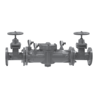
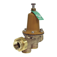
This manual describes the installation, maintenance, and repair of the Watts Series 909 and LF909 Reduced Pressure Zone Assemblies, available in sizes from 3/4" to 2". These devices are designed to protect potable water supplies from contamination due to backflow, ensuring the safety of drinking water.
Function Description:
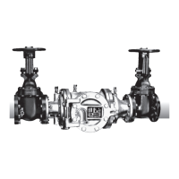
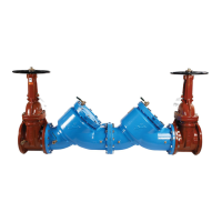
The Watts Series 909 and LF909 are Reduced Pressure Zone (RPZ) backflow preventers. Their primary function is to prevent the backflow of non-potable water into the potable water supply system. This is achieved through a unique design that incorporates two independently operating check valves and an automatically operating differential pressure relief valve located between the check valves. The relief valve is designed to maintain a pressure in the zone between the two check valves that is at least 2 psi lower than the supply pressure. This "reduced pressure zone" acts as a buffer, and if either of the check valves fails or if a backpressure condition develops, the relief valve opens to discharge water to atmosphere, thereby preventing contaminated water from entering the potable supply.
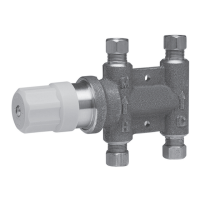
A key feature of the 909QT/LF909QT High Capacity Relief Series is its unique relief valve construction, which incorporates two channels: one for air and one for water. When the relief valve opens, the right-hand channel admits air to the top of the reduced pressure zone, relieving any zone vacuum. Simultaneously, the left-hand channel drains the zone to atmosphere. This air-in/water-out principle is crucial for stopping potential backflow, even if both check valves foul and simultaneous negative supply and positive backpressure conditions develop. This robust design ensures reliable protection against both backpressure and backsiphonage.
Usage Features:
These backflow preventers are suitable for a wide range of applications where protection against health hazards is required. They can be installed in both indoor and outdoor settings. For indoor installations, the device can be installed either vertically or horizontally, with the critical level of the relief valve positioned below the first check valve. This flexibility in orientation simplifies installation in various piping configurations. When installed indoors, it is crucial to ensure the valve is easily accessible for testing and servicing, and a drain line with an air gap should be piped from the relief valve connection to prevent water damage and ensure visible discharge in case of malfunction.
For outdoor installations in areas without freezing conditions, the device can be installed above ground. In areas prone to freezing, an insulated enclosure, such as a WattsBox, is recommended to protect the unit. Regardless of the installation location, it is imperative to comply with all state and local codes, including requirements for an air gap below the relief port to prevent cross-connection due to flooding or submersion of the assembly.
The manual also addresses parallel installations, where two or more smaller size valves can be piped in parallel to serve a larger supply pipe main. This configuration is beneficial for systems requiring increased capacity or for maintaining service during testing or servicing of individual valves without shutting down the entire line. Prior to installation, thorough flushing of all pipe lines is recommended to remove foreign matter that could foul the device. During startup, the upstream shutoff should be opened slowly to fill the backflow preventer, bleeding air at each test cock, and then the downstream shutoff should be slowly opened to fill the water supply system. This gradual process prevents dislodging O-rings or damaging internal components.
Maintenance Features:
Regular inspection and maintenance are critical for the continued effectiveness of the Series 909 and LF909. The product must be tested periodically in compliance with local codes, but at least once per year or more frequently if service conditions warrant. Corrosive water conditions, unauthorized adjustments, or improper repairs can render the product ineffective. Regular checking and cleaning of internal components help assure maximum life and proper function.
The manual provides detailed test procedures for the Reduced Pressure Assembly, including tests for Check Valve No. 2 tightness, Shutoff Valve No. 2 tightness, Check Valve No. 1 tightness, and the Pressure Differential Relief Valve operation. These tests require a certified tester and specific steps involving needle valves and test cocks to accurately assess the device's performance.
Servicing the check valves and relief valve is designed to be straightforward, requiring no special tools for the Series 909/LF909. The manual outlines steps for disassembling, cleaning, and reassembling the first and second check valves, as well as the relief valve. For check valves, the process involves removing screws, lifting the cover, rotating the check valve module to disengage components, cleaning or replacing the disc assembly and O-rings, and then reassembling. It is important to note that the springs and covers of the first and second check valves are not interchangeable, with the heavier spring-loaded module belonging in the first check.
For the relief valve, the procedure involves removing bolts, the cover, and the stainless steel adapter, then pulling out the relief valve assembly. The relief valve seat and disc can be cleaned without full disassembly. If replacement is needed, the relief valve module can be readily disassembled without special tools. The manual also includes a "To Prevent Shaft Damage Assemble As Shown" section with illustrations, emphasizing the importance of proper alignment during reassembly to avoid bending the shaft.
A comprehensive troubleshooting guide is provided to help diagnose and resolve common issues such as periodic spitting or continual dripping from the vent, high pressure drop, no water flow, improper testing, rapid fouling, and winterization. Solutions range from cleaning or replacing components to installing additional devices like strainers or soft-seated check valves, or implementing winterization measures like heat-tape wrap or complete removal of the body if the supply line is not used during winter. Repair kits and service parts are readily available and can be found on the manufacturer's website. For technical assistance, customers are advised to contact their local Watts representative.