Do you have a question about the Watts 900 Series and is the answer not in the manual?
Step-by-step guide for cleaning the first check valve using maintenance tools and safely opening the access door.
Procedure for safely removing the first check valve assembly using specialized tools and handling precautions.
Instructions for disassembling the second check valve module, including handling safety and component removal.
Method to open the access door when the maintenance tool cannot be fully inserted due to relief valve position.
Lists the components included in the service parts kit for the Series 900 backflow preventer.
Legal disclaimer regarding chemicals known to cause cancer or birth defects in California.
Details the manufacturer's warranty terms, exclusions, and limitations for the product.
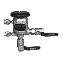
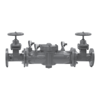
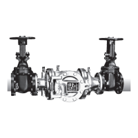
The Watts Series 900 Reduced Pressure Principle Backflow Preventer is a critical device designed to protect potable water supplies from contamination due to backpressure or backsiphonage. Its primary function is to prevent the reverse flow of non-potable water into the clean water system, ensuring the safety and integrity of the public water supply. This device is essential in various applications, including commercial, industrial, and irrigation systems, where there is a potential for cross-connection between potable and non-potable water sources.
The backflow preventer operates on a principle that maintains a pressure differential across its internal components. It features two independently acting check valves, which are the core of its protective mechanism. The first check valve is located upstream and is designed to close if the water pressure drops or reverses. The second check valve, positioned downstream, provides an additional layer of protection. Between these two check valves is a relief valve that is designed to open and discharge water to the atmosphere if the pressure in the zone between the check valves drops below the supply pressure, or if either check valve leaks. This design ensures that any potential backflow is safely vented, preventing it from entering the potable water system.
Usage features of the Watts Series 900 are designed for straightforward installation and reliable operation. The device is typically installed in the main water line where a potential cross-connection exists. It requires proper sizing and installation according to local plumbing codes and regulations to ensure effective protection. The instruction manual emphasizes the importance of inquiring with governing authorities for local installation requirements, highlighting the need for compliance to maintain water safety standards. For Australia and New Zealand, a specific note advises installing line strainers between the upstream shutoff valve and the inlet of the backflow preventer, which helps protect the device from debris and ensures optimal performance. The device is built with robust materials to withstand varying water pressures and environmental conditions, contributing to its long-term reliability.
Maintenance features are a significant aspect of the Watts Series 900, ensuring its continued functionality and compliance with safety standards. Regular testing and maintenance are crucial for backflow preventers. The manual provides detailed procedures for both quick cleaning operations and the removal of check valve assemblies for more thorough inspection and part replacement.
For quick cleaning of the first check valve, the process involves inserting a maintenance tool into the vent port, closing both inlet and outlet gate valves, and opening the test cocks to equalize pressure. This allows the access door to be opened, providing access to the first check valve seat and discs for inspection and cleaning. The manual advises wiping these components with a clean cloth and checking for any damage or deterioration.
When more extensive maintenance or part replacement is needed, such as the removal of the first check valve assembly, specific tools like the assembly tool and T-bolt tool are utilized. The procedure involves inserting the assembly tool into the relief valve casting and screwing it onto the check valve assembly. The wing nut of the assembly tool is then tightened just enough to allow the maintenance tool to be removed from the vent port. This process helps to decompress the springs safely before the check valve assembly is fully removed. The manual provides a caution against over-tightening the wing nut, as this can damage the relief valve disc. Once the assembly is removed, parts can be replaced, and the reassembly process is the reverse of removal, with a reminder to lubricate the seat gasket with O-ring grease.
Dismantling the second check valve also involves a careful procedure. The valve stem is depressed and held open to collect any water spillage. Access through the door allows for wiping both the seat and disc of the second check assembly. If damage is found, six bolts from the flange of the second check valve module are removed to take out the module. A special procedure is outlined for situations where the relief valve is open and the maintenance tool cannot be fully inserted into the vent port. This involves using a T-bolt tool to secure the relief valve casting, allowing the access door to be opened safely even with spring load.
The manual also provides a list of service parts kits, which typically include first and second check valve discs, a set of O-rings, and silicone grease, facilitating easy replacement of common wear parts. For field testing procedures and troubleshooting, the manual directs users to specific supplementary documents, indicating a comprehensive support system for the product. Technical assistance is also available through local Watts representatives, ensuring that users have access to expert help when needed.
Overall, the Watts Series 900 Reduced Pressure Principle Backflow Preventer is a robust and reliable device designed for critical water protection. Its design incorporates multiple layers of defense against backflow, and its maintenance procedures are clearly outlined to ensure longevity and consistent performance, making it a dependable solution for maintaining water quality.
| Brand | Watts |
|---|---|
| Series | 900 |
| Inlet Size Range | 1/2" - 2" |
| Outlet Size Range | 1/2" - 2" |
| Temperature Range | 33°F - 180°F |
| End Connections | Threaded |