4
NOTES: 1. No special tools are required to service the Series 919
1
⁄4" - 2".
2. Before servicing, make sure the water is turned off or shutoff valves are closed.
The following procedures provide information for replacing the diaphragm, the relief valve disc, and
the relief valve seat. It is recommended that you visually inspect these parts to determine if a
replacement or a cleaning is required.
Disassembling the Relief Valve
1. Remove the relief valve cover bolts while holding the cover down.
2. Turn the cover counterclockwise for
1
⁄4 turn, and lift it straight off
while still applying pressure to the cover with your hand.
W
ARNING
Make sure you apply pressure to the cover as you lift it straight off. Due to the release
of pressure when removing the cover, the relief valve spring may eject quickly.
3. Remove the relief valve assembly (includes cover O-ring, stem and diaphragm assembly).
4. Remove the relief valve spring.
5. Remove the pressed in relief valve seat and seat O-ring.
Replacing the Diaphragm
6. Using a wrench, loosen the diaphragm assembly by turning
the hex bolt counterclockwise.
7. Remove the diaphragm and replace with a new diaphragm
if required, or clean the existing diaphragm.The molded step
of the diaphragm should point down towards the relief valve stem.
8. Using a wrench, reassemble the diaphragm assembly
by turning the hex bolt clockwise to tighten.
Replacing the Relief Valve Disc and Seat
9. Using a phillips screwdriver, remove the screw in the relief valve
disc and replace the disc if required, or clean the existing disc.
10.Place the screw back into the relief valve disc and tighten.
11.Replace the relief valve seat with a new seat if required, or
clean the existing seat.
Reassembling the Relief Valve
12.Place the relief valve seat back into the chamber bore.
13.Slide the diaphragm assembly into the relief valve seat.
14.Place the spring on to the diaphragm assembly.
15.Place the cover O-ring on the diaphragm assembly.
16.Line up the grooves on the relief valve cover with the grooves in the
relief valve body, and turn the cover clockwise
1
⁄4 turn to seat the cover.
17.Using a wrench, place the bolts back into the cover and tighten.
CAUTION
If the cover does not lie flat against the relief valve body, the diaphragm assembly is not installed
properly and damage can result. Remove the bolts and cover, realign the diaphragm assembly,
and place the cover back on the relief valve body.
18.Open the shutoff valves.
Servicing the Relief Valve
1
⁄4" – 2" (8 – 50mm)
Replacement Parts
1
⁄4" – 2" (8 – 50mm)
When ordering, specify Ordering Code Number, Kit number and Valve Size.
ORDERING CODE KIT NO. SIZE
in. mm
Total Relief Valve Kits:
0888130 RK 919 VT
1
⁄4 –
1
⁄2 8 – 15
0888131 RK 919 VT
3
⁄4 – 1 20 – 25
0888132 RK 919 VT 1
1
⁄4 – 2 32 – 50
Kit consists of: Relief Valve Assembly, RV Spring, and RV Cover O-ring
Relief Valve Rubber Parts Kits:
0888135 RK 919 RV
1
⁄4 –
1
⁄2 8 – 15
0888136 RK 919 RV
3
⁄4 – 1 20 – 25
0888137 RK 919 RV 1
1
⁄4 – 2 32 – 50
Kit consists of: Relief Valve Disc, RV Diaphragm, RV Seat O-ring and Cover O-ring
ORDERING CODE KIT NO. SIZE
in. mm
Relief Valve Seat Kits:
0888150 RK 919 SV
1
⁄4 –
1
⁄2 8 – 15
0888151 RK 919 SV
3
⁄4 – 1 20 – 25
0888152 RK 919 SV 1
1
⁄4 – 2 32 – 50
Kit consists of: Relief Valve Seat, RV Seat O-ring and RV Cover O-ring
Relief Valve Cover Kits:
888155 RK 919 VC
1
⁄4 –
1
⁄2 8 – 15
888156 RK 919 VC
3
⁄4 – 1 20 – 25
888157 RK 919 VC 1
1
⁄4 – 2 32 – 50
Kit consists of: Relief Valve Cover and Cover O-ring
Air Gaps
0881575 919 AGA
1
⁄4 –
1
⁄2 8 – 15
0881576 919 AGC
3
⁄4 – 1 20 – 25
0881577 919 AGF 1
1
⁄4 – 2 32 – 50
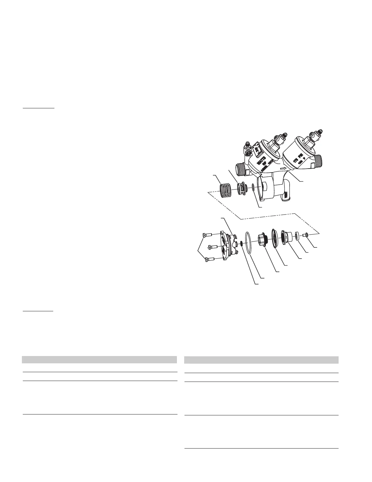
Quad-Ring
Relief Valve Cover O-ring
Diaphragm Nut
Relief Valve Diaphragm
Relief Valve Stem
Relief Valve Disc
Relief Valve
Disc Screw
Relief Valve Seat
Body
Relief Seat O-ring
Relief Valve
Spring
Relief
Valve
Cover
Cover
Bolts
 Loading...