3
W
ARNING
Do not allow the drain line to empty directly into a drainage ditch, sewer system,
or sump.
NOTE: Relief Valve Discharge Rates
The Series 919 air gap and drain line terminating above a floor drain can accom-
modate any moderate discharge or nuisance spitting through the relief valve.
However, to prevent water damage in the case of a catastrophic failure, you may
need to design the floor drain size to accommodate the increased discharge.
Refer to Figure 1 for maximum relief valve discharge rates, size, and capacity of
typical floor drains.
NOTE: DO NOT reduce the size of the drain line from the air gap fitting. The drain
line must remain at full line size.
E. After initial installation of the Series 919, a discharge from the relief valve may
occur due to dirt and pipe compounds. This may be due to inadequate initial
flushing of the pipe lines. If flushing the valve does not clear the unit, remove
the first check valve and clean thoroughly, using the procedures in "Servicing
First & Second Check Valves" on page 5.
NOTE: Periodic relief valve discharge may occur on dead end service applications,
such as boiler feed lines or cooling tower makeup lines. This may be due to fluc-
tuating supply pressure during a static or no flow condition. To avoid this dis-
charge, install a spring-loaded, rubber seated check valve ahead of the backflow
assembly.
F. It is recommended that you not place the Series 919 in a pit or at a depth below
the ground level, unless absolutely necessary. If an installation requires below
ground level installation, a modified pit installation is recommended, as well as
the approval of local codes. In such cases, provision should be made to always
vent the drain line above the flood level. In the case of a pit drain, ensure an
adequate air gap exists between the bottom of the drain line and the bottom of
the pit.
G. It is recommended that periodic inspection of the Series 919 be done to
check for any discharge from the relief valve. This discharge is a visual indica-
tion that the valve needs cleaning or repair. In addition, it is recommended that
periodic testing of the valve be done in compliance with local codes to ensure
its proper operation.
The relief vent discharges water during no-flow periods when:
(1) the first check valve is fouled; or
(2) the inlet pressure to the check valve drops sufficiently due to upstream pres-
sure fluctuations. This then affects the required operating differential between
the inlet pressure and the reduced pressure zone; or
(3) the second check is fouled during emergency backflow or resulting from a
water hammer condition.
For troubleshooting guide send for literature S-TSG.
NOTE: When installing the Series 919 on fire prevention systems, special consid-
erations are required.
Fire Protection System Installations: The National Fire Protection Agency (NFPA)
Guidelines require a confirming flow test be conducted by a certified tester when-
ever a “main line” valve is installed, such as a shutoff valve or a backflow preventer.
Basic Installation Instructions
1
⁄4" – 2" (8 – 50mm)
Typical Flow Rates as sized by floor drain manufacturers:
2" 55 GPM 5" 350 GPM
3" 112 GPM 6" 450 GPM
4" 170 GPM 8" 760 GPM
A. Shutoff Valves: If you remove the shutoff valves from the Series 919, reassemble the shutoff
valve with the test cock mounted on the inlet side of the unit.
B. Always install the Series 919 in an accessible location to facilitate testing and servicing (See
Page 2). *Check the state and local codes to insure that you install the backflow preventer in com-
pliance with those codes, such as the proper height above the ground.
C. It is recommended that you install a strainer ahead of the Series 919 assemblies to protect
the internal components from unnecessary fouling.
CAUTION
Do not install a Series 919 with a strainer in rarely used water lines, such as a fire sprinkler sys-
tem which is only used during emergencies.
Start Up: Close the downstream shutoff. Open the upstream slowly and fill the valve. When the
valve is filled, open the downstream shutoff slowly, and fill the water supply system. This is nec-
essary to avoid water hammer and/or shock damage.
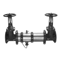
D. Vent the air gap and drain line from the relief valve in accordance with code requirements.
Terminate discharge approximately 12" (300mm) above the ground or through an air gap
piped to a floor drain.
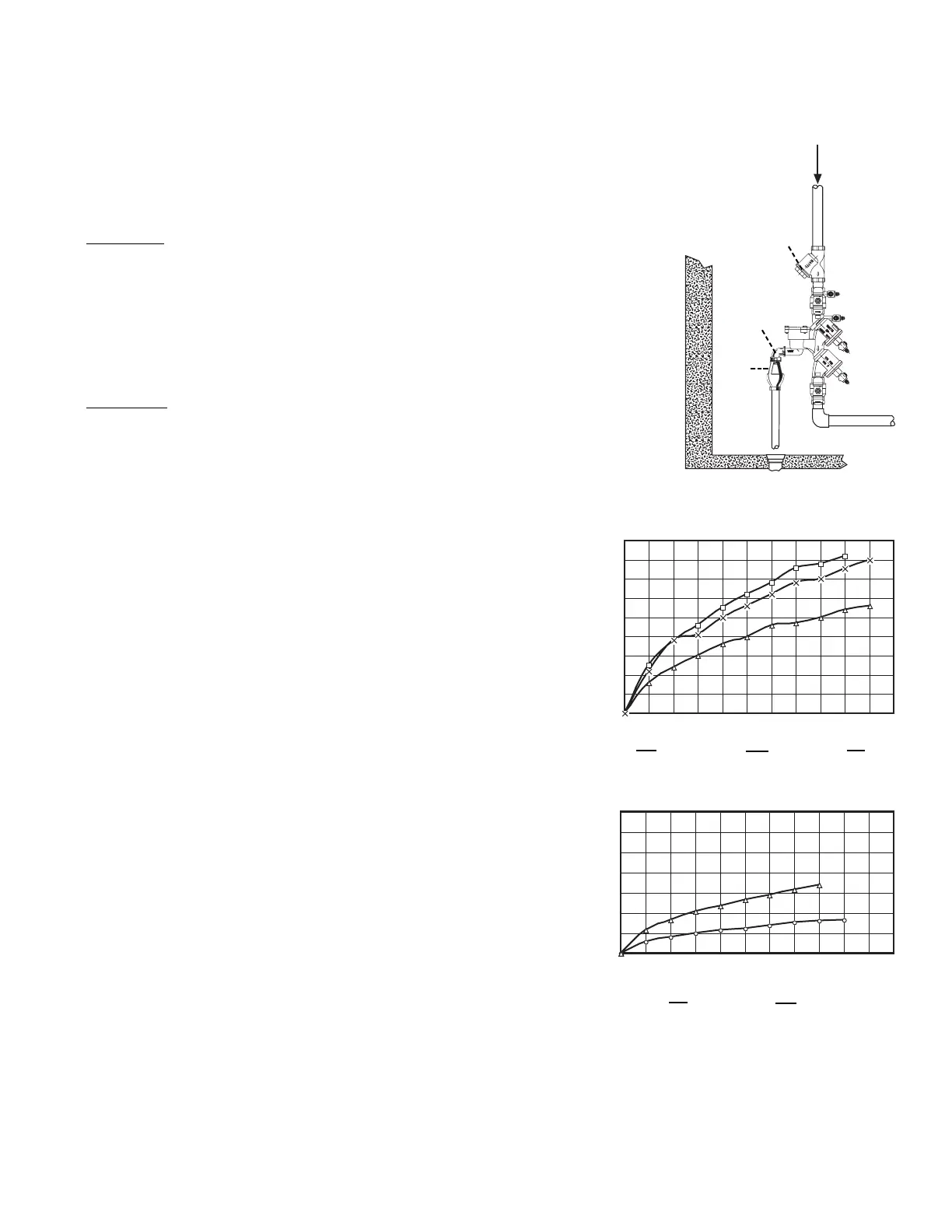
45
40
35
30
25
20
15
10
5
0
0 10 20 30 40 50 60 70 80 90 100 150
Flow Rate gpm
Flow Rate gpm
Zone Pressure psi
0 10 20 30 40 50 60 70 80 90 100 150
Zone Pressure psi
1
⁄4" – 1" (8 – 25mm) 919
Watts
1
⁄4" – 2" 919
*Vertical Flow Down
1
1
⁄4" – 2" (32 – 50mm) 919
350
300
250
200
150
100
50
0
Floor Drain
Air
Gap
Elbow
Strainer
1
⁄4"–
1
⁄2"
3
⁄4"X 1"
0 1
1
⁄4"–1
1
⁄2" 2"
(8 – 15mm) (20mm) (25mm)
(32 – 40mm) (50mm)
 Loading...