EasyManua.ls Logo

Watts LF23B Series - User Manual

Watts LF23B Series
2 pages
Print Icon
To Next Page IconTo Next Page
Loading...
Instructions for Installing Series LF23B,
LF123LP, LFN250 and LFN250B
Water Pressure Reducing Valves
Install Valve in the line with arrow on valve body pointing in the
direction of flow.
This valve should be installed where it is accessible with suf-
ficient clearance for cleaning, service or adjustment. Install
the reducing valve, when possible, before the sill cock line as
shown in diagram. Before installing the reducing valve, flush out
the line to remove loose dirt and scale which might damage
valve disc and seat.
Horizontal installation is recommended. However, valve can be
installed in a vertical position. Regulator must be installed in an
accessible location to facilitate servicing the regulator.
To readjust reduced pressures, loosen adjusting screw nut and
turn adjusting screw clockwise to raise reduced pressure and
counterclockwise to lower reduced pressure.
When reducing valve is used, it makes a closed system;
therefore, pressure relief protection must be provided on the
downstream side of the reducing valve to protect equipment.
CAUTION
!
Anytime a reducing valve is adjusted, the use of a pressure
gauge is recommended to verify correct pressure setting. Do
not bottom out adjusting screw or spring cage.
Servicing
This series is a new development for standard capacity domes-
tic water regulation service. It has special unitized construc-
tion which consists of the seat, disc and stem assembly, and
strainer screen all together in one unit for complete replacement
maintenance.
To clean or replace parts.
1. Remove spring cage and all parts above diaphragm.
2. Loosen and remove diaphragm lock nut, lock washer,
pressure plate, and diaphragm from valve stem.
3. Unscrew seat cylinder from body and remove entire assem-
bly. For diaphragm replacement only, see part number.
4. While disassembled open gate valve to flush out collected
sediment.
NOTICE
Cast iron body regulators (LFN250/LFN250B) are not intended
for buried or pit services.
Main Line Service
Cold Water Supply
Reducing Valve
To Sill Cock
From Street Main
Meter
Adjusting Screw
Adjusting Screw Nut
Spring Cage
SA135B116
Bypass
Assembly for
models “B”
Diaphragm
(Size 1⁄2" - 560CA20)
(Size 3⁄4", 1" - 23B20)
Diaphragm
Lock Nut and
Pressure Plate
Name Plate
Complete Replacement Assembly
See reverse side for ordering information
Stem
Seat Cylinder
Integral
Stainless Steel
Valve Seat
Disc
Strainer
Screen
IS-2323A
WARNING
!
Read this Manual BEFORE using this equipment.
Failure to read and follow all safety and use information
can result in death, serious personal injury, property
damage, or damage to the equipment.
Keep this Manual for future reference.
Question and Answer IconNeed help?

Do you have a question about the Watts LF23B Series and is the answer not in the manual?

Overview

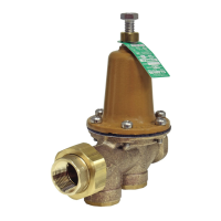
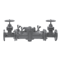
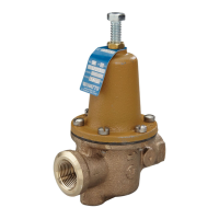
The Watts Series LF23B, LF123LP, LFN250, and LFN250B are water pressure reducing valves designed to regulate domestic water pressure. These devices are crucial for maintaining consistent water pressure in a system and protecting downstream equipment from excessive pressure.

Function Description

These valves are installed in the main water line, typically after the street main and before the sill cock line, to reduce high incoming water service pressure to a more manageable and consistent level for household use. The valve's internal mechanism, including a diaphragm, spring, and disc, works to maintain a set reduced pressure on the downstream side. When the downstream pressure exceeds the set point, the valve closes further to restrict flow, and when it drops, the valve opens to allow more water through, thus regulating the pressure.

A key feature of the LF23B, LF123LP, LFN250, and LFN250B series is the "Bypass" model, which incorporates an integral thermal expansion bypass check valve. This bypass is designed to mitigate the effects of thermal expansion in closed water systems. In a closed system, when water is heated (e.g., in a water heater), it expands, causing an increase in pressure. Without a bypass, this pressure increase can lead to the relief valve (on the water heater) dripping. The integral thermal expansion bypass allows the expanding water to flow back into the supply main when the thermal expansion pressure increases by just 1 to 2 lbs. higher than the main pressure. This effectively dissipates the expanding water, similar to an open system, and reduces the frequency of relief valve dripping. It's important to note that while this bypass feature limits relief valve dripping, it does not replace the need for a pressure relief valve to protect against other causes of excessive pressure. The effectiveness of the bypass is also limited to systems where the street main pressure is less than the allowable setting of the pressure relief valve.

Important Technical Specifications

The valves are available in various sizes, including 1/2" and 3/4", to accommodate different plumbing requirements. Specific ordering codes and kit numbers are provided for replacement parts, such as:

  • 1/2" LFN250RK (Ordering Code 878377): For LF23, LF123, LFN250 models.
  • 3/4" LFN250RK (Ordering Code 878339): For LF23, LF123, LFN250, LFN256 models.

These kits include the complete replacement assembly, which typically consists of the diaphragm, stem, seat cylinder, strainer screen, disc, and integral stainless steel valve seat.

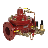
The cast iron body regulators (LFN250/LFN250B) are specifically noted as not being intended for buried or pit services.

Usage Features

  • Installation: The valve must be installed in the line with the arrow on the valve body pointing in the direction of flow. Horizontal installation is recommended, but vertical installation is also possible. It should be installed in an accessible location to facilitate servicing and adjustment. Before installation, the line should be flushed to remove loose dirt and scale that could damage the valve disc and seat.
  • Pressure Adjustment: To readjust reduced pressures, the adjusting screw nut needs to be loosened. Turning the adjusting screw clockwise will raise the reduced pressure, while turning it counterclockwise will lower the reduced pressure. A pressure gauge is recommended during adjustment to verify the correct pressure setting. It is crucial not to bottom out the adjusting screw or spring cage.
  • Closed System Consideration: When a reducing valve is used, it creates a closed system. Therefore, pressure relief protection must be provided on the downstream side of the reducing valve to protect equipment from excessive pressure buildup.

Maintenance Features

The LF23B, LF123LP, LFN250, and LFN250B series feature a "unitized construction" for easy maintenance. This design integrates the seat, disc, stem assembly, and strainer screen into a single unit, simplifying replacement.

To clean or replace parts:

  1. Remove the spring cage and all parts above the diaphragm.
  2. Loosen and remove the diaphragm lock nut, lock washer, pressure plate, and diaphragm from the valve stem.
  3. Unscrew the seat cylinder from the body and remove the entire assembly.
  4. While disassembled, open the gate valve to flush out any collected sediment.

For diaphragm replacement only, specific part numbers are available (e.g., Size 1/2" - 560CA20, Size 3/4", 1" - 23B20). A complete replacement assembly, including the diaphragm, stem, seat cylinder, strainer screen, disc, and integral stainless steel valve seat, is available for comprehensive maintenance.

Safety Information

A warning emphasizes the importance of reading the manual before using the equipment, as failure to follow safety and use information can result in death, serious personal injury, property damage, or damage to the equipment. The manual should be kept for future reference.

A California Proposition 65 warning is included, stating that the product contains chemicals known to the State of California to cause cancer and birth defects or other reproductive harm. Further information is available at www.watts.com/prop65.

Watts LF23B Series Specifications

General IconGeneral
BrandWatts
ModelLF23B Series
CategoryControl Unit
LanguageEnglish

Related product manuals