LMSW-105
Digital Lighting Management
Low Voltage Scene Switch
THIS UNIT IS PRESET FOR
PLUG n’ GO OPERATION,
ADJUSTMENT IS OPTIONAL.
For full operational details, adjustment and more
features of the product, see the DLM System
Installation Guide at www.wattstopper.com
Installation shall be in accordance with all applicable
regulations, and codes.
To be connected to a Class 2 power source only.
Class 2 Device Wiring Only – Do Not Reclassify and Install
as Class 1, or Power and Lighting Wiring.
Wire connections shall be rated suitable for the wire size
(lead and building wiring) employed.
Voltage ....................................................24VDC
Current Consumption ................................5mA
Power Supply ..WattStopper Room Controllers
Connection to the DLM Local
Network ...................................... 2 RJ-45 ports
DLM Local Network characteristics when using
LMRC-2xx/3xx room controllers:
Low voltage power provided over Cat 5e cable
(LMRJ); max current 800mA. Supports up to 64
load addresses, 48 communicating devices including up to 4 LMRC-10x
series and/or LMPL-101 controllers. Free topology up to 1,000’ max.
Environment ....................................................... For Indoor Use Only
Operating Temperature ..........................32° to 131°F (0° to 55°C)
Storage Temperature ............................ 23° to 176°F (-5° to 80°C)
Relative Humidity .................................5 to 95% (non condensing)
Patent Pending
CONNECTIVITY
The illustrations show examples of free-topology wiring.
The LMSW-105 communicates with all other Digital Lighting
Management devices connected to the low voltage DLM
Local Network.
Quick Start Guide
Line Voltage
Line Voltage
J-Box
Occupancy Sensor
LMRC-212
Dimming
Room
Controller
LMDM-101
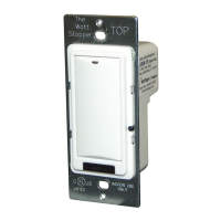
Dimming Switch
LMDM-101
Dimming Switch
LMSW-105
Scene Switch
Class 2 0-10 Volt Control Wiring
0-10 Volt
Ballast
0-10 Volt
Ballast
LMRJ Cables
Corner Mount
Occupancy
Sensor
Switch/
Dimme
Ceiling Mount
Occupancy
Sensor
LMRJ from
Room
Controller
J Box
To
Load
DLM Local Network
(low voltage, Class 2)
LMRJ cables
LMRC-21x
Room
Controller
To 0-10V
Dimming Ballast
Daylighting
Sensor
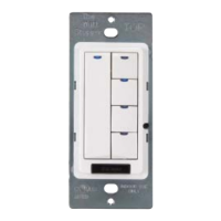
MOUNTING THE SWITCH
Red LED
Blue Status LEDs
Scene Button (4)
Conguration Button
(behind switch plate)
Tap when load OFF:
Turn ON to last level
Tap when load ON:
Go to full bright
Press & Hold:
Ramp Up
Tap when load ON:
Turn OFF
Press & Hold:
Ramp Down
BUTTONS AND INDICATORS
WARNING: Do Not Install To Cover a Junction Box
Having Class 1, 3 or Power and Lighting Circuits.
SPECIFICATIONS
When all loads bound to the dimmer paddle are OFF, it’s
Blue status LED is dim. When any load bound to the dimmer
paddle is ON it’s Blue status LED is bright.
When a scene is active the LED on the scene button is bright.