EasyManua.ls Logo

wattstopper LVSW Series - User Manual

wattstopper LVSW Series
2 pages
Print Icon
To Next Page IconTo Next Page
Loading...
LVSW-101/102/103/104/108
Low Voltage Switch
Voltage, from panel .............................................. 24VDC, Class 2
Maximum Contact Current Per Button ............................... 50mA
Maximum Operating Current ................................................ 2mA
Wire Connections; Removable Terminal Blocks
Use 18 -22 AWG Copper Conductors Only
One terminal per button
One terminal per LED
Two common terminals; shared with all buttons and LEDs
Environment ................................................. For Indoor Use Only
Operating Temperature ....................32° to 130°F (0° to 55°C)
Relative Humidity ........................... 5 to 95% (non condensing)
UL and cUL listed
Installation Instructions
LVSW-108LVSW-104LVSW-103LVSW-102LVSW-101
The LVSW series low voltage switch is intended for use with
lighting control devices that expect a momentary contact
closure to toggle the state of the lighting load. Each button
on the LVSW switch has an LED indicator intended to display
the current state of the lighting load when connected
appropriately to the lighting control device. Five color kits and
custom engraving options are available.
WIRING
P2
1
1
P1
COM
SW1
SW2
SW3
SW4
SW5
SW6
SW7
SW8
COM
LED1
LED2
LED3
LED4
LED5
LED6
LED7
LED8
Common
Switch button
Button LED
SPECIFICATIONS
1. Connect the “Com” terminal (common) of the LVSW switch to the lighting control
device per the instructions provided with the device. Note that both “Com” terminals
on the LVSW switch are internally connected together.
2. Connect the terminal corresponding to the button on the LVSW switch (SW1 –SW8) to
the input of the lighting control device per the instructions provided with the lighting
control device.
3. Connect the terminal corresponding to the LED pilot light on the LVSW button (LED1 –
LED8) to the pilot light output of the control device per the instructions provided with
the lighting control device.
4. Repeat for all buttons on the switch. Refer to diagram for button-terminal cross
reference.
5. Install the LVSW switch into a single gang wall box or one position in a multi-gang
switch box using the mounting screws provided with the LVSW switch. Be careful to
press the low voltage wires into the box so they are not pinched by the mounting plate.
6. Install an appropriate switch cover plate (not supplied) over the LVSW switch to
complete the installation.
MOUNTING THE SWITCH
BUTTONS AND INDICATORS
On/Off button
Blue LED
WARNING: Do Not install To Cover Junction Box Having Class 1,
3 or Power and Lighting Circuits.
WARNING  For install in UL Listed Junction Box or Enclosure
Containing Only Class 2 Wiring - Do not Reclassify and Install as
Class 1, 3 or Power and Lighting Wiring.
Back View
Question and Answer IconNeed help?

Do you have a question about the wattstopper LVSW Series and is the answer not in the manual?

Summary

Product Introduction and Specifications

Specifications

Details voltage, current ratings, wire types, and environmental conditions for the switch.

Switch Installation and Wiring

Mounting the Switch

Instructions and diagrams for physically installing the low voltage switch.

Mounting Warnings

Critical safety warnings regarding junction box compatibility and wiring class.

Wiring and Connections

Guidance on connecting switch terminals and understanding button/LED indicators.

Button-Terminal Cross Reference

Overview

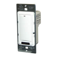
The LVSW series low voltage switch is designed for use with lighting control devices that require a momentary contact closure to toggle the state of the lighting load. Each button on the LVSW switch includes an LED indicator that displays the current state of the lighting load when connected appropriately to the lighting control device. These switches are available in five color kits, and custom engraving options are also offered.

Function Description:

The LVSW switch acts as an input device for lighting control systems, providing momentary contact closures to signal changes in lighting states. The integrated LED indicators provide visual feedback on the current status of the controlled lighting loads. The switches are designed for indoor use and are UL and cUL listed, ensuring compliance with safety standards.

Important Technical Specifications:

  • Voltage: 24VDC, Class 2 (from panel)
  • Maximum Contact Current Per Button: 50mA
  • Maximum Operating Current: 2mA
  • Wire Connections: Removable Terminal Blocks
    • Requires 18-22 AWG Copper Conductors Only
    • One terminal per button
    • One terminal per LED
    • Two common terminals, shared with all buttons and LEDs
  • Environment: For Indoor Use Only
  • Operating Temperature: 0° to 55°C (32° to 130°F)
  • Relative Humidity: 5 to 95% (non-condensing)

Usage Features:

Mounting the Switch:

The LVSW switch is designed for installation in standard junction boxes. It is crucial to note the following warnings:

  • WARNING: Do NOT install to cover a junction box having Class 1, 3, or power and lighting circuits.
  • WARNING: For installation in UL Listed junction boxes or enclosures containing ONLY Class 2 wiring, do not reclassify and install as Class 1, 3, or power and lighting wiring.

The switch is installed into a single-gang wall box or one position in a multi-gang switch box using the provided mounting screws. Care should be taken to press the low voltage wires into the box to prevent them from being pinched by the mounting plate. An appropriate switch cover plate (not supplied) is then installed to complete the installation.

Wiring Instructions:

  1. Common Connection: Connect the "Com" terminal (common) of the LVSW switch to the lighting control device according to the device's instructions. Both "Com" terminals on the LVSW switch are internally connected.
  2. Button Input Connection: Connect the terminal corresponding to each button on the LVSW switch (SW1 - SW8) to the input of the lighting control device as per its instructions.
  3. LED Output Connection: Connect the terminal corresponding to the LED pilot light on each LVSW button (LED1 - LED8) to the pilot light output of the control device as per its instructions.
  4. Repeat for all buttons: Follow steps 2 and 3 for all buttons on the switch. A diagram is provided for button-terminal cross-reference.

Button and Indicator Features:

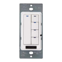
Each LVSW switch features one or more on/off buttons, depending on the model (LVSW-101, LVSW-102, LVSW-103, LVSW-104, LVSW-108). Each button is accompanied by a blue LED indicator. This LED illuminates to show the current state of the controlled lighting load, providing immediate visual feedback to the user.

Models and Button Configurations:

  • LVSW-101: Features one button (SW1).
  • LVSW-102: Features two buttons (SW1, SW2).
  • LVSW-103: Features three buttons (SW1, SW2, SW3).
  • LVSW-104: Features four buttons (SW1, SW2, SW3, SW4).
  • LVSW-108: Features eight buttons (SW1-SW8).

Maintenance Features:

The device itself does not specify any particular maintenance features. Given its nature as a low-voltage switch, maintenance would typically involve ensuring clean connections and proper operation of the buttons and LEDs. In case of malfunction, troubleshooting would likely involve checking wiring connections and the associated lighting control device. The robust design for indoor use and UL/cUL listing suggest a durable product with minimal maintenance requirements under normal operating conditions.

wattstopper LVSW Series Specifications

General IconGeneral
Brandwattstopper
ModelLVSW Series
CategorySwitch
LanguageEnglish

Related product manuals