10
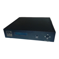
3.1 Indicators, Control and Connections
PAINT DATA (1):
Indicator; Paint Data when connected with base station
CCU (2):
Camera Control Unit (CCU) button control and display for paint system
HDMI(3):
HDMI input with embedded audio and video input
Tally:
External RED and GREEN tally is available when using the Tally Camera Interface. Tally
Connector (ring-tip –sleeve) LED voltage for Bi-Level Tally indicator
Data:
The camera control unit (CCU) connects to the camera using the supplied data cable.
This is a LEMO 4 pin female, RS-232 date for CCU camera paint. (Thompson/Grass
Valley)
Paint:
The camera control unit (CCU) connects to the camera using the supplied data cable.
This is a Hirose 7 pin female, RS-422 data for CCU camera paint. (Sony)
Audio 1 & Audio 2:
XLR Connectors; (x2) Analog audio In
HD/SDI:
BNC Connector; for HD/SDI Video Input
When power is applied the CP splash screen should appear and then the Unit Status
will be displayed.
 Loading...