Do you have a question about the Wave Central PAINT TX and is the answer not in the manual?
Explains how to connect the RCP-TX-IDU to the TX ODU and camera tally interface.
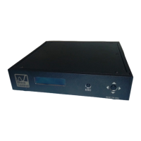
Describes the status display of the ODU, including port connections and tally notifications.
Details how to access and select camera manufacturers via the unit's menu.
Explains how to remotely control frequency and power output of the TX ODU from the RCP-TX-IDU.
Guides on how to select and set the radio frequency for the system.
Details how to choose and program the desired power output level for the transmitter.
Covers checking and updating software and firmware versions using a PC.
Explains power supply, data connection via Ethernet, and antenna connection for the TX-ODU.
Explains the indicators, controls, and various connection types on the AXTX1 unit.
Describes the unit status indicators for Camera, Data RX, Camera ID, and Tally.
Explains the importance of setting the correct camera number for proper control and operation.
| RX RF In | SMA female |
|---|---|
| TX RF Out | N type connector |
| HDMI | HDMI type A connector, video and audio input |
| External Tally Out | 1/8” Phone jack (Ring tip sleeve) |
| Data | LEMO 4 pin female RS-232 data to camera CCU |
| Paint | Hirose 7 pin female RS-422 data to camera CCU |
| Audio 1 | XLR female audio connector, audio input |
| Audio 2 | XLR female audio connector, audio input |
| HD/SDI | BNC HD/SDI Video in |
| Frequency | 403 – 474 MHz Programmable from front panel |
|---|---|
| Channel Bandwidth | 12.5 KHz |
| Modulation | GMSK (Gaussian Minimum Shift Keying) |
| TX Power | 100/200/500/1000mW Selectable front panel RCP-TX-ODU |
| Data Interface | RS485 9600 baud |
| Power In | 120VAC 60 Hz 25 Watts |
|---|
| DATA | Ethernet Type B wiring |
|---|---|
| CCU | DB9 female connector |
| Tally | Dual - Ethernet Type B wiring |
| USB | USB Type B |
| Power In | 6 – 17VDC |
|---|
| DATA PWR | Ethernet Type B wiring |
|---|---|
| Antenna | SMA female connector |
| FCC ID | MRBSATEL-TA13G |