13
Appendix 1
Connectors
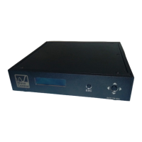
RCP-TX-IDU
DATA: Ethernet Type B wiring
CCU 1: DB-9 pin female connector
CCU 2: DB-9 pin female connector
CCU 3: DB-9 pin female connector
CCU 4: DB-9 pin female connector
Note: Above connect to camera remote control panel (RCP)
TALLY: Dual Ethernet Type B, wiring for RED and GREEN
USB Type B: Used for firmware updates via computer
120/240 V: AC Input
TX-ODU
DATA PWR: Ethernet Type B wiring
Antenna: SMA female connector
TALLY INTERFACE
USB: Ethernet Type B wiring RED
USB: Ethernet Type B wiring GREEN
Push Connectors:
Camera 1: 2 Pair Red|Black RED|GREEN
Camera 2: 2 Pair Red|Black RED|GREEN
Camera 3: 2 Pair Red|Black RED|GREEN
Camera 4: 2 Pair Red|Black RED|GREEN
 Loading...