132
GENERATOR
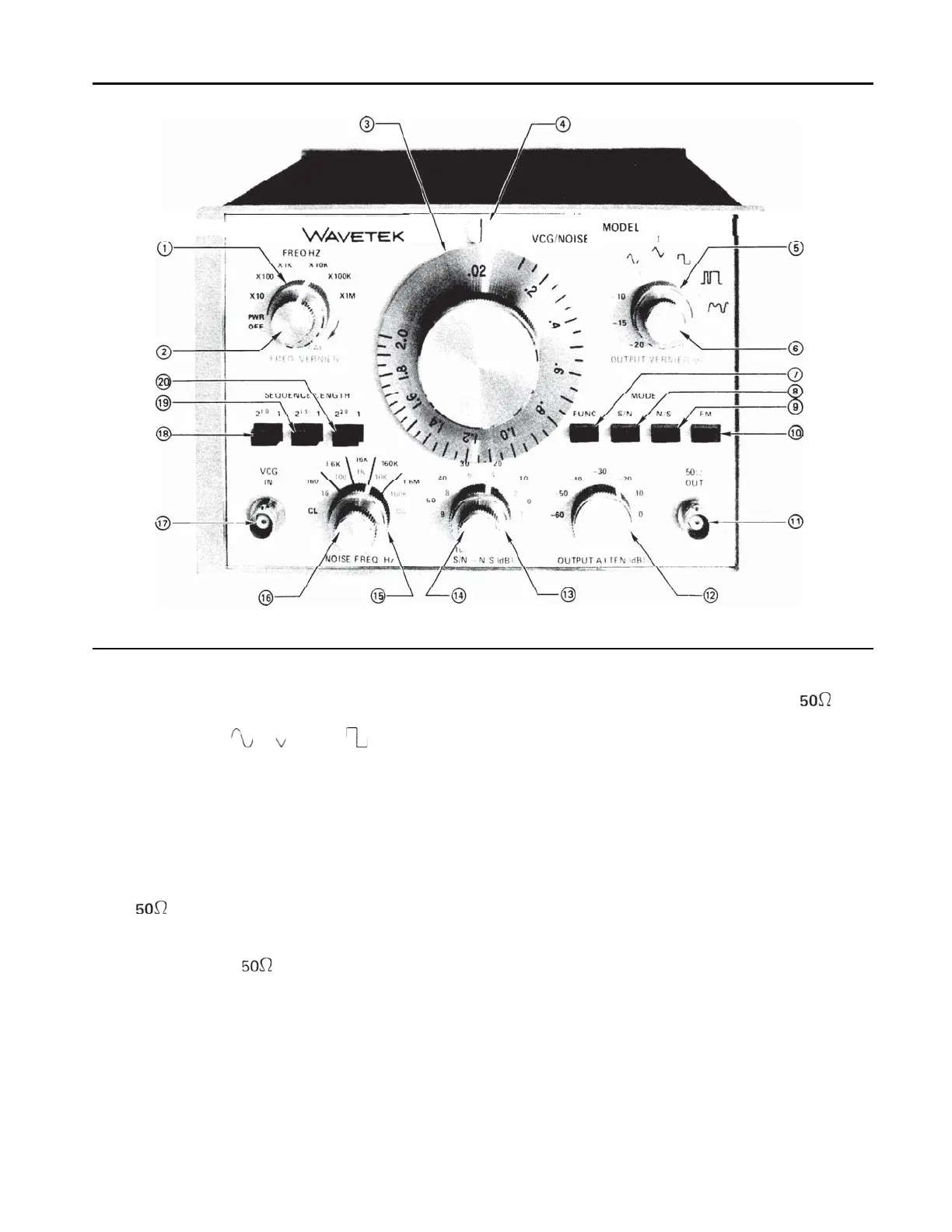
Figure 2-l. Operating Controls, Front Panel
10.
11.
12.
FM
-
Depressing this push button along with
the FUNC push button (7) allows the selected
signal, either
A
, ,
or wave, to be
pseudo-randomly frequency modulated, or jit-
tered. The modulating signal is provided by
pseudo-random analog noise, and the S/N
-
N/S
(dB)
controls frequency deviation. The
bandwidth of the modulating signal is controlled
by the NOISE
FREQ
HZ selector (15) and
vernier (16).
OUT
-
Provides the selected generator out-
put function. The generator may operate into an
open circuit providing 20 V peak to peak maxi-
mum, or into a
load providing a
10
V peak
to peak output.
OUTPUT
ATTEN
(dB)
-
Attenuates the output
(both signal and noise) from 0
dB
to -60
dB
in
six calibrated 10
dB
steps according to the fol-
lowing table:
Step
Attenuator
Position
Output peak to peak into
Load
Maximum Minimum
Vernier Vernier*
fully cw
0
dB
10V
IV
-10
dB
3V
0.3 v
-20
dB
I V 0.1 v
-30
dB
0.3 v 0.03 v
-40
dB
0.1 v
0.01 v
-50
dB
0.03 v 0.003 v
-60
dB
0.01 v 0.001 v
* The values in this table are approximate. The OUT-
PUT VERNIER
(dB)
(6) will reduce the output
approximately 20
dB
in all cases, as shown.
13.
S/N
-
N/S (dB)
-
I n
the S/N
mode, this control
attenuatesthe analog noise from
0 to
-50
dB
in
five calibrated 10
dB
steps. The selectable signal
5