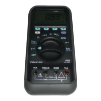
CONTINUITY TEST
The Continuity test checks electrical continuity between two contact
points. ❶ Set the Function switch to position. ❷ Connect black
test lead to COM input and red lead to VΩ input. ❸ Connect probe tips to
two circuit points. ❹ The internal beeper emits a tone when resistance is
less than approx. 100Ω.
D • Durchgangstest
❶ Funktionsschalter auf stellen. ❷ Rotes Meßkabel mit VΩ Eingang und
schwarzes mit COM Eingang verbinden. ❸ Meßspizen mit Schaltkreis verbinden.
❹ Akustisches Signal bei R ≤100Ω.
E • Prueba de continuidad
❶ Ponga el selector de función/escala en la posición . ❷ Conecte la punta
de prueba negra a la entrada COM y la punta de prueba roja a la entrada VΩ. ❸
Toque dos puntos del circuito con las puntas de prueba. ❹ El zumbador suena
cuando la resistencia es ≤100 Ω.
F • Test de Continuité
❶ Placez le sélecteur sur . ❷ Connectez le cordon rouge à l’entrée VΩ et
le noir à l’entrée COM. ❸ Connectez les pointes de touche au circuit. ❹ U n e
résistance de ≤100kΩ est indiquée par un signal sonore.
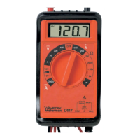
DIODE AND TRANSISTOR TEST (See Fig. 4)
The diode test measures the voltage drop across a diode junction. ❶
Connect the test leads as shown in figure 4. ❷ Set the Function/range
switch to . ❸ Apply probe tip of red lead to the anode and of black
lead to the cathode of the diode. The meter’s display indicates the forward
voltage drop (approx. 0.6V for silicon diode or 0.4V for germanium
diode). A short tone indicates a good diode. An open diode is indicated
by “OPEN”. ❹ Reverse test lead connections to the diode to perform a
reverse bias test. “OPEN” indicates a good diode. N o t e s : “OPEN” for
both reverse and forward bias tests indicates an open diode. A low
voltage reading for both bias tests indicates a shorted diode. If the diode
is shunted by a resistor of 1000 ohms or less, it must be removed from
the circuit before taking the measurement. Bipolar transistor junctions
may be tested in the same manner described above as emitter-base and
base-collector junctions are diode junctions.
D • Dioden- und Transistortest (siehe Fig. 4)
Der Diodentest zeigt den Spannungsabfall über den Diodendurchgang ❶
Meßkabel wie in Figur 4 verbinden. ❷ Funktionsschalter auf stellen. ❸
– 18 –
2020/30.Man.3x5,25/XPr 19/06/97 14:36 Page 20
 Loading...