Général: Avant de
connecter ou de
déconnecter les cordons
de test, coupez
l’alimentation du circuit
mesuré et déchargez les
condensateurs.
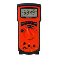
RESISTANCE
MEASUREMENT
(See Fig. 1)
❶ Turn off power to the
resistance to be measured
and discharge any
capacitors. Any voltage
present during a resistance
measurement will cause
inaccurate readings.❷
Connect red test lead to
+Rx Input (red) and black test lead to -Rx Input. ❸ Set Function/Range Switch
to the desired Ω position. ❹ Connect test leads to resistance or circuit to be
measured. ➎ Read resistance value on Digital Display. Open circuits will be
displayed as an overload condition.
Note: On the 20Ω range, an adjustment potentiometer (ZERO ADJ.) allows you
to zero out the test lead resistance. Short test leads and adjust the knob until
the display reads zero.
D • Widerstands
messung (siehe Fig. 1)
❶
Es darf keine Spannung am Widerstand anliegen. Kondensatoren
entladen. Eine Spannung würde die Messung verfälschen.
❷
Rotes
Meßkabel mit +Rx Eingang (rot) und schwarzes mit -Rx verbinden.
❸
Funktionsschalter auf gewünschte Ω Position stellen.
❹
Meßspitzen mit
Schaltkreis verbinden.
➎
Meßwert ablesen. Eine offene Schaltung wird mit
Überlast angezeigt.
– 8 –