CHAPTER 12 CLICK 172/174 141
Note
If outputs 1 and 2 on the Click 174 have been configured to the same lane, then out-
puts 3 and 4 cannot be configured to monitor two dierent lanes.
5 Aer the lanes have been congured, move the Settings switch to position 3 (Run Set-
ting).
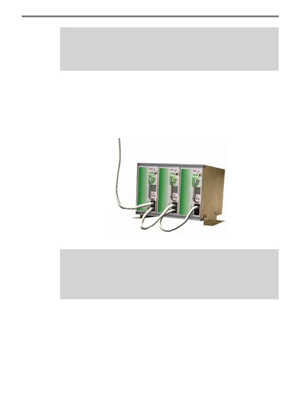
6 Congure all remaining Click 172/174 cards individually and then connect them in
a daisy chain from the rst card’s RJ-11 port to the next card’s RJ-11 port using the
4-inch RJ-11 jumper cables (see Figure 12.7). Any Click 172/174 card in the rack can be
selected as the rst card, as long as the above daisy chain procedure is followed starting
from that card.
Figure 12.7 – Cards Daisy-chained Together
Note
The last Click 172/174 card’s RJ-11 jack will have an unconnected jack. However, if the
cable run from the SmartSensor to the Click 172/174 card is greater than 500 feet,
then a terminator will need to be attached to the unconnected slot.
Verify Operation
When the Settings switch is in position 3 (Run Setting), the card is listening to data pushed
by the SmartSensor. All other communication or noise being transmitted by other devices
is ignored, including SmartSensor Manager. However, depending on your conguration,
SmartSensor Manager may temporarily disable data push while the SmartSensor Manager
connection is active. During this time, contact closures will cease.