184 CHAPTER 22 CLICK 250
Physical Features
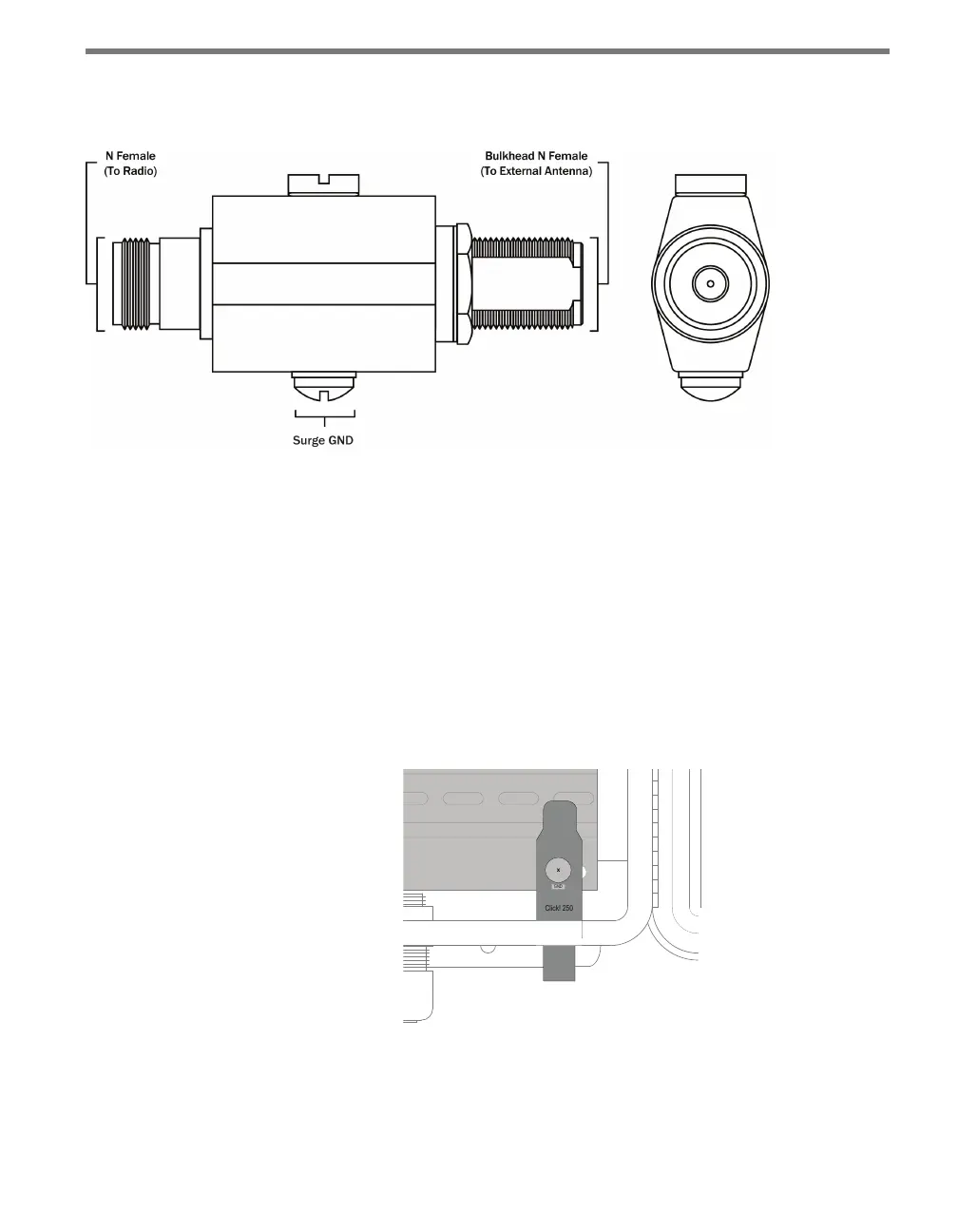
Figure 22.2 – Diagram of the Click 250
e Click 250 is a bulkhead N-Female to N-Female connector; both connector ports are
equally protected. e ground lug and terminal are located directly on the housing of the
Click 250.
Installation
e Click 250 should be mounted in the wall (usually the bottom) of a cabinet, in a ⅝” hole.
Wavetronix berglass cabinets come with such holes predrilled; aluminum cabinets do not
and a hole will need to be drilled. It is recommended that the hole be in the bottom of the
cabinet, on the far right.
Figure 22.3 – Click 250 in Wall of Cabinet
Follow the steps below to install a Click 250.
1 Connect a 12 AWG stranded copper grounding wire to the surge GND bolt, as shown
below. ere are two bolts on the Click 250; use the bolt with the rounded top.