62 CHAPTER 4 CLICK 104
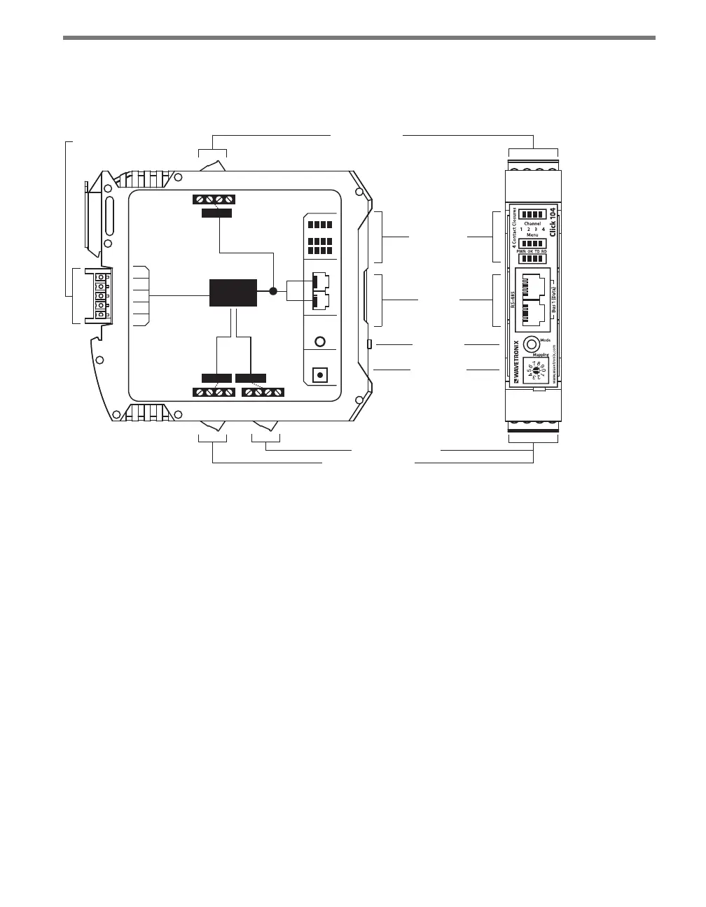
Physical Features
e Click 104 has the following physical features.
T-Bus
Connector
RS-232 Connector
Outputs 1-2 Connector
Mode Switch
RS-485
Connector
LED Indicators
Rotary Switch
Outputs 3-4 Connector
FRONT
TOP
RS-232
3-4 1-2
LEDs
RS-485
Bus 2
Control
Contact
Closures
+DC
-DC
+485
-485
GND
Bus 1
Data
Bus 1
Data
104
Click
Mode
Switch
Rotary
Switch
Figure 8.2 – Diagram of Click 104
Communication Ports
e Click 104 has two independent serial communications buses. Bus 1, also referred to
as the data bus, should be used to report vehicle data; its associated communication ports
consist of two RJ-11 jacks, for RS-485, on the faceplate and one screw terminal, for RS-232,
on the top of the device.
Bus 2, also referred to as the control bus, should be used for conguration. Its associated
communication port is the a 5-position connector, located on the back of the Click 104, that
plugs into a T-bus connector and provides power and RS-485 communication to the device.
It also passes RS-485 communication from the Click 104 to all other devices on the T-bus.
Contact Closure Outputs
e contact closure outputs should be wired to a controller, data logger or BIU (Bus In-
terface Unit) using the pluggable screw terminals on the bottom of the Click 104. ere
are two screw terminal blocks; the one closer to the faceplate has outputs 1 and 2, and the
farther one has outputs 3 and 4. Each output consists of two terminals, one + and one –.
e screw terminal connectors can also be unplugged from the Click 104 allowing you to