APPENDIX 47
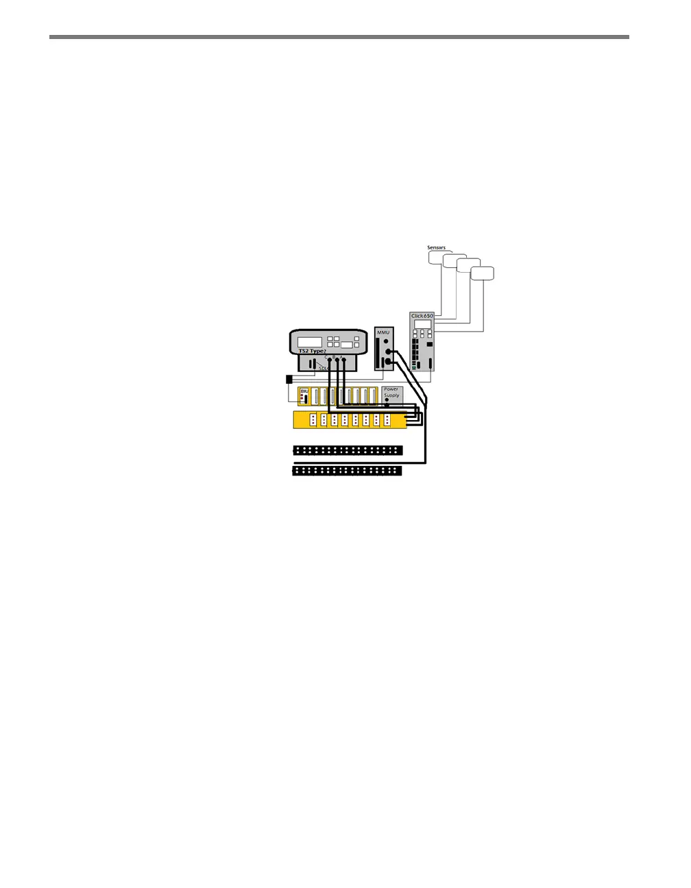
TS2 Type 2 – e controller provides connectors to the SDLC bus and to the A, B, C
harnesses. e minimum requirement is that the controller and the MMU be connect-
ed through the SDLC bus. SmartSensors are interfaced to the bus through the SDLC
bus of the Click 65x or can be connected through patch cables to contact closures in a
card rack connected to the bus through a BIU. is design works well when four (Click
650) or six (Click 656) Wavetronix sensors are connected through the Click 65x’s SDLC
bus utilizing 64 channels of detection. If additional sensors are needed, they are con-
nected to contact closure cards via patch cables through a backplate or Click 600. If
necessary, two Click 65x devices can be used with both Advance and Matrix connected
to the bus through the units’ SDLC ports, bridged together.
Figure A.2 – TS2 Type 2
The system operation for TS2 Type 2 when operating like a TS1 or when used with
a TS1 – e controller oers TS1 operating mode with the MMU and/or CMU operat-
ing in TS1 mode. Detectors, load switches, ash relays and ashers also operate in TS1
mode with each connected to the A, B, C harnesses. SmartSensors are interfaced with
the controller through a Click 600 or backplate through patch cables to contact closure
devices which are connected via the wiring harnesses. e Click 65x can be used in
this conguration without SDLC. e Click 65x’s built-in Ethernet provides network-
ing and communication advantages, with the ability to use the same equipment if the
cabinet or controller are upgraded in the future.
 Loading...