46 APPENDIX
also provided a D connector which was manufacturer-specic. ese are oen referred to
as harness connectors as this is where the wiring harnesses for the cabinets are terminated.
TS1 controllers receive detection inputs through contact closure cards usually found in
racks wired in the cabinet and connected to the front of the controller. Shelf mount contact
closures were also used where racks were not available. Wavetronix sensors can interface to
these controllers using either a backplate-to-contact-closure connection or by using a Click
600 series cabinet interface device to connect the contact closure outputs. e wiring from
the contact closures to the controller is pre-wired in the cabinet.
TS2 controllers were formally approved by both NEMA and IMSA in 1992 and became the
ocial successor to the TS1 controllers. TS2 was updated in 1998 and again in 2003 when
NTCIP was added to the standard. In order to accommodate a transition from TS1 pin con-
nectors A, B, C, and D, two types of TS2 controllers were developed.
Type 1 is a pure TS2 controller and was intended for new system installations. ese con-
trollers can only communicate via SDLC. Some TS2 Type 1 cabinets still use detector racks
but provide their inputs to the SDLC in the controller through a BIU in the card rack.
TS2 Type 2 controllers are widely used because of the exibility of placing them into either
a TS1 or TS2 cabinet. ese provide both an SDLC connection and the front pin connectors
A, B, C and D.
Either type of TS2 cabinet provide for better standardization. It includes coordination, pre-
emption, time based control, automatic ash & telemetry hardware. It species all connec-
tions inside the trac cabinet and species physical layer of system-level communications.
How Can TS2 Controllers Utilize Click 65x Series
Devices?
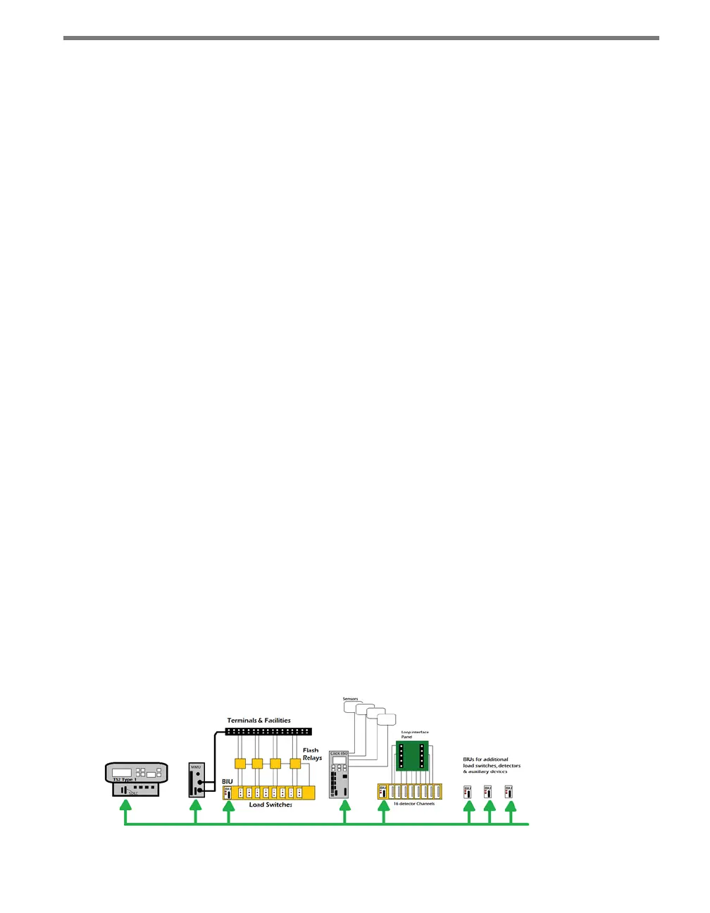
TS2 Type 1 – e SDLC serial data bus replaces A, B and C harnesses. e bus serves
as the data highway for the cabinet. Load switches, loop detectors, and preemption are
interfaced to the bus through BIUs. SmartSensors are interfaced to the bus through
the SDLC bus of the Click 65x. e MMU retains point-to-point wiring to load switch
outputs.
Figure A.1 – TS2 Type 1
 Loading...