WX-500-0315
© 2019 Wavetronix LLC. All rights reserved. Protected in the US by patents viewable at www.wavetronix.com/en/legal. Protected by Canadian Patent Nos. 2461411; 2434756; 2512689; and European Patent Nos. 1435036;
1438702; 1611458. Other US and international patents pending. Wavetronix, SmartSensor, Click, Command and all associated logos are trademarks of Wavetronix LLC. All other product or brand names as they appear are
trademarks or registered trademarks of their respective holders. Product specifications are subject to change without notice. This material is provided for informational purposes only; Wavetronix assumes no liability
related to its use.
4
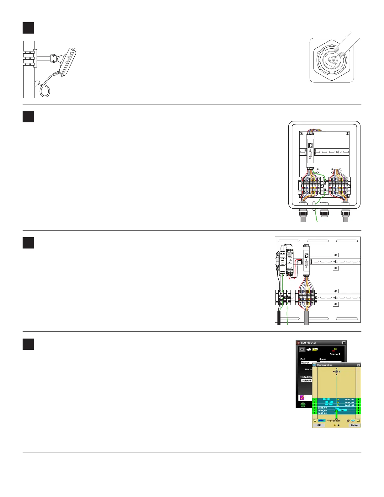
Attach the cable
1 Tear the tab o the tube of silicon dielectric compound that came with the sensor.
2 Squeeze about half of the compound on the connector at the base of the sensor.
3 Insert the cable connector into the sensor connector. Be aware it’s a keyed connector.
4 Twist the cable connector clockwise until you hear it click into place.
5 Run the cable through the pole. Leave a small amount of slack at the top; this
reduces strain and allows you to create a drip loop.
6 If there’s excess cable, don’t cut it, as you may need it in the future; leave it in the pole.
6
Set up the trac cabinet
5
Set up the pole-mount box
Note. Not all installations will include a pole-mount box; if yours doesn’t, disregard this section.
1 Use the included mounting brackets, and Band-It or a similar clamping system, to attach the Surge
Preassembled Cabinet to the pole.
2 Insert the sensor cable (pigtail cable coming from the sensor) through the rightmost cable grip on
the bottom of the box; twist the grip to tighten.
3 Terminate the conductors in the terminal blocks marked “To SmartSensor,” following the color
scheme on the labels; do not strip the insulation on the conductors.
4 Insert one end of the homerun cable (the cable that runs to the trac cabinet) through the lemost
grip, and twist the grip to tighten.
5 Repeat step 3 with the terminal blocks marked “To Trac Cabinet.”
6 Make sure the box is grounded.
Lightning
Surge
Protection
W
ProtectedProtected
Click!
200
RS-485RS-232 DCE
To SmartSensor
GNDGNDRDTDCTSRTSGND
485+485-GND-DC+DC
To Trac Cabinet
GNDGNDRDTDCTSRTSGND
485+485-GND-DC+DC
GNDGNDRDTDCTSRTSGND485+485-GND-DC+DCGNDGNDRDTDCTSRTSGND485+485-GND-DC+DC
1 Use the included screws to mount the Standard Preassembled Backplate in the trac cabinet.
2 Terminate the conductors from the power cable into the terminal blocks marked “110 VAC,”
following the color scheme on the labels; do not strip the insulation on the conductors.
3 Terminate the conductors from the homerun cable into the terminal blocks marked “Smart-
Sensor,” following the color scheme on the labels; do not strip the insulation on the conductors.
4 Make sure the backplate is grounded.
Note. e backplate includes a Click 200, which has RS-232 and RS-485 ports for communications.
If you’d like to use a dierent Click communication device, mount it on the DIN rail.
Lightning
Surge
Protection
W
ProtectedProtected
Click!
200
RS-485RS-232 DCE
110 VAC
SmartSensor
GNDGNDRDTDCTSRTSGND
485+485-GND-DC+DC
L N G
GL
GNDGNDRDTDCTSRTSGND485+485-GND-DC+DC
7
Check alignment in the SmartSensor Manager HD software
9
Connect to SmartSensor Manager HD
1 Make a wired or wireless connection between your laptop and one of the Click 200s in the installation.
2 Launch SSMHD and click Connect on the main menu. Based on the kind of connection you’re mak-
ing, go to the Serial or Internet screen. Change any necessary settings, and click Connect.
3 On the main SSMHD screen, click the Lanes button, then click Conguration.
4 Click the magnifying glass icon to open the View menu, then click Show Alignment. To see an arrow
for each lane, click the sidebar button until the number 1 appears.
5 Watch the arrows to see where the sensor’s alignment is at.
6 If necessary, move the sensor manually to x it. Give the soware a few moments aer each sensor move-
ment to adjust; a few vehicles need to pass by before it can report on the new alignment.
Note. For conguration instructions, see the SmartSensor HD User Guide.
 Loading...