EasyManua.ls Logo

Webasto Air Top 2000 ST D User Manual

Webasto Air Top 2000 ST D
48 pages
To Next Page IconTo Next Page
Page #1 background imageLoading...
Page #1 background image
Improper installation or repair of Webasto heating and cooling systems can cause
fire or the leakage of deadly carbon monoxide leading to serious injury or death.
Installation and repair of Webasto heating and cooling systems requires special
Webasto training, technical information, special tools and special equipment.
NEVER attempt to install or repair a Webasto heating or cooling system unless you
have successfully completed the factory training course and have the technical skills,
technical information, tools and equipment required to properly complete the
necessary procedures.
ALWAYS carefully follow Webasto installation and repair instructions and heed all
WARNINGS.
Webasto rejects any liability for problems and damage caused by the system being
installed by untrained personnel.
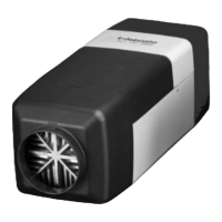
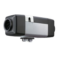
Air Heater
Air Top 2000 ST D (Diesel)
Air Top 2000 ST B (Gasoline)
Service and Repair Manual

Table of Contents

Questions and Answers:

Webasto Air Top 2000 ST D Specifications

General IconGeneral
Heater TypeAir Heater
Fuel TypeDiesel
Voltage12V / 24V
Heat Output2 kW (7, 000 BTU/h)
Operating Temperature Range-40°C to +40°C (-40°F to +104°F)

Summary

Introduction

Contents and Purpose

Overview of the manual's content and the heater's intended use and applications.

Meaning of Signal Words

Explanation of DANGER, WARNING, CAUTION, and NOTE signal words used in the manual.

Additional Documentation

Information on whether other documentation is required for repairs.

Safety Information and Regulations

General safety regulations, accident prevention, and statutory requirements for heater installation.

Suggestions for Improvements and Changes

Contact information for submitting suggestions or corrections to the manual.

General Description

Drive Unit

Description of the drive unit components, including the motor, blowers, and intake casing.

Heat Exchanger

Explanation of how heat is transferred from combustion to the air via the heat exchanger.

Burner Insert with Combustion Pipe

Details on the burner insert, fuel distribution, and combustion process.

Control Unit

Role of the control unit as the central component for heater operation and monitoring.

Flame Sensor (Gasoline Heaters Only)

Function of the flame sensor in monitoring the flame status via resistance changes.

Ceramic Glow Pin

Explanation of the glow pin's function in igniting the fuel-air mixture during startup.

Overheating Sensor

How the overheating sensor monitors temperatures and protects the heater.

Fuel Metering Pump

Description of the fuel metering pump's function in supplying fuel to the heater.

Functional Description

Control Element (Rheostat)

How the control element switches the heater on/off and adjusts room temperature.

Switch On

Step-by-step process of switching the heater on, including glow plug and blower operation.

Heating Mode

Description of how combustion heat is transferred to the cabin air during operation.

Control Mode

How blower speed and metering pump rate adjust based on heat output.

Control Pause

Explanation of how the heater reduces output and pauses operation when the set temperature is reached.

Switch Off

Procedure for switching the heater off and the LED indicator status.

Fault Lock-out

Conditions under which the heater switches off and enters fault lock-out mode.

Technical Data

Troubleshooting

General

Introduction to identifying and remedying faults on the Air Top 2000 ST heater.

General Error Symptoms

Table listing common error symptoms, their possible causes, and remedies.

Error Symptoms during Function

Table detailing specific error symptoms that occur during heater operation and their solutions.

Error Code Output

Explanation of error codes displayed on timers and their corresponding remedies.

Functional Tests

General

Overview of tests performed on the heater to verify its functionality.

Settings

Details on adjusting heater settings, specifically the CO2 content.

Testing Individual Components

Procedures for testing specific components like the glow pin and flame sensor.

Circuit Diagrams

General

Information on circuit diagrams for 12V and 24V systems with control elements or timers.

Servicing Work

General

Introduction to the servicing tasks for maintaining heater functionality.

Work on the Heater

Precautions and steps for performing work on the heater itself.

Work on the Vehicle

Safety precautions related to working on the vehicle while the heater is installed.

Heater Trial

Guidelines and warnings for testing the heater after installation or servicing.

Servicing Work

Recommended servicing intervals and checks for the heater.

Visual Inspections and Installation Instructions

Procedures for visual checks and guidance on installation aspects.

Removal and Installation

Step-by-step instructions for removing and installing the heater unit.

Start-up

Procedures for bleeding the fuel system and conducting a trial run after installation.

Repair

General

General guidance on repair work and using spare parts.

Work on Stripped-down Components

Procedures for cleaning and visually inspecting components after dismantling.

Carrying Out Modifications

Information on modifications and installing an external temperature sensor.

Dismantling and Assembling

Detailed steps for dismantling and reassembling the heater casing parts.

Product Information

WARRANTY COVERAGE AND LIMITATIONS

Related product manuals