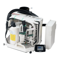
Roof-top air-conditioning system CC8 2 General description
207
As the liquid refrigerant flows through the receiver-drier (7) to the expansion valve (14), it decompresses with the
controlled drop in pressure and returns to the gaseous state in the evaporator (2), absorbing considerable heat at the
same time.
The warm air (4) circulating in the cabin is drawn in by the radial fan (5), cooled in the evaporator, dried and returned
to the cabin via the air ducting system or the air distribution panel (1). Accumulated condensation water is separated
out and routed to the exterior by means of drain hoses.
During operation, the refrigerant circuit is monitored via an anti-icing switch and a pressure switch. These two switches
control the magnetic clutch to engage and disengage the compressor.
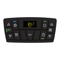
When the air-conditioning system is switched off via the ON / OFF rocker switch, the magnetic clutch and fan motors
are de-energized, and the refrigerant and air circuits are deactivated.
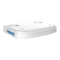
The open design of the roof-top unit allows rainwater entering its wet area to drain from the vehicle roof.
2.7 Design, purpose and principle of operation of the assemblies
2.7.1 Condenser
The condenser (15, Fig. 202) consists of a continuous pipe coil and fins interconnected to form a large heat exchanger
surface.
The condenser cools the hot refrigerant gas so that it condenses and undercools. The condensation heat is transmitted
via the fins to the outside air flowing through the condenser.
2.7.2 Receiver-drier
The receiver-drier (9, Fig. 202) with viewglass is a refrigerant compensation and reservoir vessel. Its lower part contains
a granulated desiccant which extracts and chemically binds small amounts of water from the refrigerant. This reduces
the risk of ice forming on the expansion valve and protects the compressor against damage. During operation, the
viewglass is used to check that there is sufficient refrigerant in the circuit.
2.7.3 Thermal expansion valve
The thermal expansion valve (6, Fig. 202) controls the refrigerant flow to the evaporator in accordance with the
refrigerant required or the temperature in the evaporator. The expansion valve is a control element between the low
and the high pressure sections of the refrigerant circuit.
2.7.4 Evaporator
The evaporator (5, Fig. 202) is basically of the same design as the condenser. The refrigerant flowing through the pipe
from the expansion valve changes from the liquid to the gaseous state and superheats in the evaporator.
The required evaporation heat is extracted from the cabin air flowing through the fins and is transmitted through the
pipe to the refrigerant. The air dries as it cools and condensation water is drained overboard. A mist separator prevents
droplets of condensation water being drawn in by the radial fan and entering the cabin interior.
2.7.5 Pressure switch
The pressure switch contains a high and a low pressure switch. It monitors the pressure conditions in the high-pressure
section of the refrigerant circuit and switches the compressor off by disengaging the magnetic clutch if the pressure is
too low (e.g. due to loss of refrigerant) or too high (e.g. overheating of condenser).
2.7.6 Anti-icing thermostat
The anti-icing thermostat (10, Fig. 202) is a temperature switch which measures the temperature between the fins of
the evaporator and disconnects the power supply to the magnetic clutch if there is a risk of ice forming (approx. 0 °C).
The power supply is reconnected at approx. + 3 °C.

 Loading...
