5 Operating information Roof-top air-conditioning system CC8
502
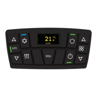
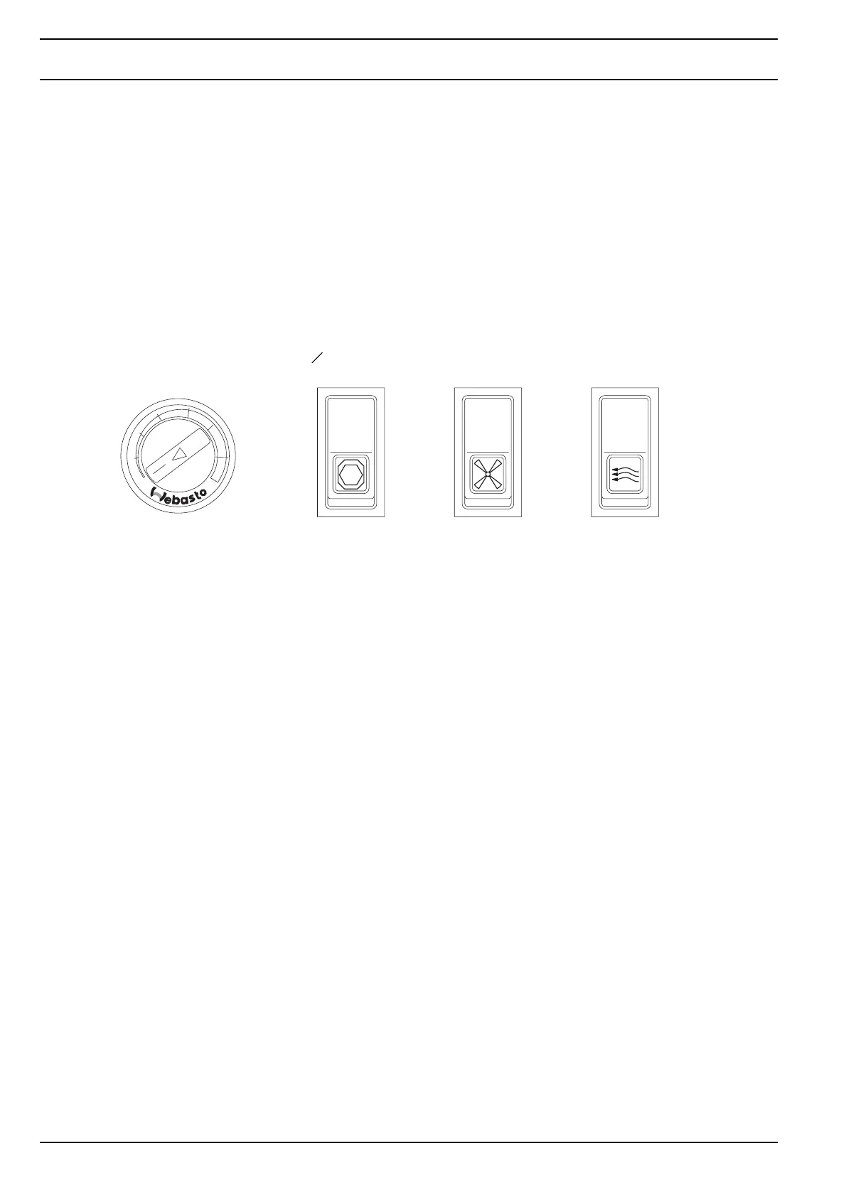
5.3 Controls and indicators
Two rocker switches (Fig. 501) are used to control the roof-top air-conditioning system. As an option a temperature con-
troller (command value switch) or a rocker switch for the fresh air ventilation flap may be installed.
– Air conditioning ON / OFF (2-position switch)
– 3-position rocker switch (fan power)
– Rocker switch (fresh air ventilation flap) (2-position switch) with illuminated indicator when open
– Command value switch (temperature controller)
The controls and indicators are preferably mounted in the air distribution panel or in the dashboard.
Fig. 501 Controls
5.4 First-time operation
1. Start the engine as directed by the manufacturer.
2. Switch on the system using the ON / OFF switch. Turn the temperature controller fully clockwise to the right.
Run the system at maximum fan power (3-position rocker switch in position 3). After 2 minutes at the latest, cold air
must stream from the air distribution panel or the air duct.
3. Reduce fan power to other stages and check air stream.
4. Systems with fresh air ventilation flap (optional):
Open the flap via the rocker switch. After a few seconds, the flap reaches the max. open position and the indicator
lights up.
5. Systems with electronic room thermostat (optional):
Turn the command value switch (temperature controller) fully counter-clockwise to the left. The compressor is
switched off as soon as the air intake temperature is below 30 °C.
MIN
MAX
CLOSED
OPEN
OFF
ON
1
3
2
Without
illumination
Without
illumination
Illuminated
when OPEN
Temperature controller Main switch Fan power stages Fresh air ventilation flap