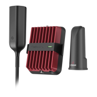
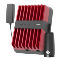
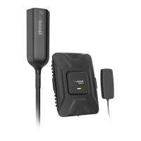
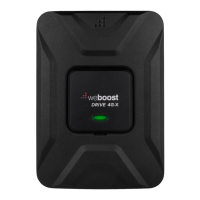
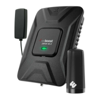
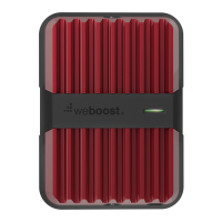
The weBoost Drive Reach OTR Cell Signal Booster is a device designed to improve cellular signal strength in vehicles. It is manufactured by weBoost, a Wilson Electronics Brand.
Function Description:
The Drive Reach OTR Cell Signal Booster amplifies existing cellular signals to provide better coverage within a vehicle. It works by connecting an outside antenna, which captures weak signals, to an inside antenna, which broadcasts the amplified signal to cellular devices within the vehicle. This process helps to reduce dropped calls, improve data speeds, and extend battery life for cellular devices in areas with poor signal. The booster is designed to function across multiple frequency bands, including 700 MHz (B12/17, B13), 800 MHz (B5), 1700 MHz (B4), and 1900 MHz (B2). It is a consumer device and requires registration with a wireless provider.
Important Technical Specifications:
- Model: 460061
- FCC ID: PWO460061
- Connectors: SMB-Jack
- Antenna Impedance: 50 Ohms
- Frequency Bands:
- 698-716 MHz
- 728-756 MHz
- 777-787 MHz
- 824-894 MHz
- 1850-1995 MHz
- 1710-1755/2110-2155 MHz
- Power Output for Single Cell Phone (Uplink) dBm:
- 700 MHz B12/17: 25.4
- 700 MHz B13: 25.6
- 800 MHz B5: 25.6
- 1700 MHz B4: 26.7
- 1900 MHz B2: 26.9
- Power Output for Single Cell Phone (Downlink) dBm:
- 700 MHz B12/17: 4.8
- 700 MHz B13: 4.8
- 800 MHz B5: 4.8
- 1700 MHz B4: 4.6
- 1900 MHz B2: 4.5
- Noise Figure: 5 dB (nominal)
- Isolation: > 90 dB
- Power Requirements: 12V 1.8A
- Outside Antenna Maximum Permissible Gain (dBi) 50Ω:
- BAND 12/17: 1.2
- BAND 13: 1.2
- BAND 5: 1.1
- BAND 4: 0.8
- BAND 25/2: 0.4
- Inside Antenna Maximum Permissible Gain (dBi) 50Ω:
- BAND 12/17: 2.1
- BAND 13: 2.6
- BAND 5: 3.20
- BAND 4: 2.1
- BAND 25/2: 2.7
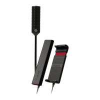
- Approved Antenna Types (Examples):
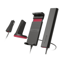
- Mobile Inside Antenna Kit Options:
- 314401 (LMR-100, 10ft, 4G Slim Low Profile SMA, 50Ω)
- 314419 (LMR-100, 10ft, 4G Slim Low Profile SMB, 50Ω)
- 311160 (RG-58, 13ft, Desktop, 50Ω)
- Mobile Outside Antenna Kit Options:
- 311215 (LMR-100, 10ft, Mini-Mag SMB, 50Ω)
- 311229 (RG-58, 15ft, 4G Trucker, 50Ω)
- 311230 (RG-6, 25ft, 4G RV OTR, 75Ω)
- 314405 (RG-58, 14ft, 4G NMO, 50Ω)
Usage Features:
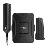
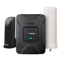
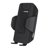
- Installation Process: The installation involves selecting mounting locations for both the outside and inside antennas, assembling the outside antenna using mast extensions and a side-exit adapter, and connecting coax cables to the booster. The outside antenna can be mounted using a 3-Way Mount for vehicles without built-in mounting points. Thread Locker is provided to secure connections. The inside antenna is mounted using a Velcro® adhesive strip, ideally 18 to 36 inches from the cellular device's usage location.
- Power Connection: The booster is powered by a 12V DC power supply cord, which plugs into the vehicle's 12V DC power supply (cigarette lighter port). The power cord has an ON/OFF switch.
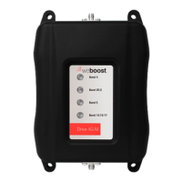
- Booster Light Patterns:
- SOLID GREEN: Indicates proper functioning and no installation issues.
- SOLID RED: Indicates a band shutoff due to oscillation (feedback loop). This is a safety feature to prevent interference with cell towers. Troubleshooting involves increasing separation between antennas.
- BLINKING RED, THEN SOLID GREEN: Indicates reduced power in one or more booster bands due to minor oscillation. If desired signal boost is achieved, no further adjustments are needed. Otherwise, troubleshooting (increasing antenna separation) is recommended.
- Light Off: Verify the power supply has power.
- Troubleshooting: For blinking or solid red light issues, the recommended steps include unplugging the power supply, relocating the inside and outside antennas further apart to increase separation distance, and then plugging the power supply back in. Horizontal separation is generally more effective than vertical separation. Customer support is available for assistance.
- Safety Guidelines:
- Use only the provided power supply.
- Do not connect the booster directly to a cell phone with an adapter.
- RF Safety Warning: Any antenna used must be at least 8 inches from all persons.
- AWS Warning: The Outside Antenna must be installed no higher than 10 meters (31'9”) above ground.
- Registration with a wireless provider is mandatory.
- Operate with approved antennas and cables only.
- Antennas must be installed at least 20 cm (8 inches) from any person.
- Cease operation immediately if requested by the FCC or a licensed wireless service provider.
- E911 location information may be inaccurate or not provided when using this device.
- Automatic Adjustments: The Signal Booster is factory set for FCC compliance and cannot be manually adjusted. It automatically reduces gain if not in use for five minutes, and automatically turns off power on a band if a signal is too high or if oscillation is detected. After 5 automatic restarts for problematic bands, they are permanently shut off until a manual restart (power cycle) is performed.
Maintenance Features:
- Resetting the Booster: The Signal Booster can be reset by disconnecting and reconnecting the power supply. This is necessary after troubleshooting to initiate a new power cycle.
- Preventing Battery Drain: If the vehicle's 12V DC power supply is always on, it is recommended to turn the booster off via the power cord switch when parking for extended periods (more than a day) to prevent battery drain.
Warranty:
The weBoost Signal Boosters come with a two (2) year warranty against defects in workmanship and/or materials. Warranty cases can be resolved by returning the product to the reseller with proof of purchase or directly to the manufacturer with a Returned Material Authorization (RMA) number. The warranty does not cover misuse, abuse, neglect, or mishandling that alters or damages the product. Replacement products may include refurbished weBoost products that meet specifications.