Do you have a question about the Wecon LX5V-2PTS-BD and is the answer not in the manual?
Same as PLC main unit, refer to accompanying manual.
Power supply is provided internally by PLC.
Details about the performance parameters of the BD module.
Covers 2-wire/3-wire PT100 connection, safety warnings, and general notes.
Specifies cable types, cross-sectional areas, and terminal tightening torque.
Illustrates the PT100 input mode and circuit diagram.
Details device allocation for LX5 series PLC and BD module configuration.
Using I/O mapping to configure the BD module functions.
Steps and interface details for configuring module parameters using host software.
Example ladder logic for programming without host configuration software.
Interface for monitoring BD module status, communication, and errors via buffer memory.
The LX5V-2PTS-BD BD Module is a specialized expansion module designed for use with PLC (Programmable Logic Controller) systems, particularly the LX3 and LX5 series. Its primary function is to provide thermal resistance input, specifically for PT100 sensors, making it suitable for applications requiring precise temperature monitoring and control. The module supports both 2-wire and 3-wire PT100 configurations, offering flexibility in sensor integration.
The core function of the LX5V-2PTS-BD BD Module is to acquire temperature data from PT100 thermal resistance sensors. It features two independent channels (CH1 and CH2), each capable of reading temperature values. The module converts the analog sensor signals into digital output, which can then be processed by the connected PLC. This digital output is expressed in units of 0.1°C, providing fine-grained temperature resolution.
For each channel, the module offers several configurable parameters to optimize performance and data accuracy. Users can enable or disable individual channels, select the sensor type (PT100 is the default), and adjust the filtering intensity. The filtering intensity helps to reduce signal jitter and improve the stability of the measured values, with options ranging from level 0 (lowest) to level 9 (highest). This allows for customization based on the specific environmental conditions and the required stability of the temperature readings.
The module also incorporates an overrun detection feature. When enabled, this function monitors whether the measured temperature exceeds predefined upper and lower limits. If the temperature falls outside this range, the host computer will generate an error prompt, alerting users to potential issues or abnormal conditions. This is a crucial safety and monitoring feature, especially in applications where temperature excursions could lead to equipment damage or process failures.
Furthermore, the LX5V-2PTS-BD supports temperature calibration. This feature allows users to compensate for deviations between the actual temperature and the measured channel value. By setting gain and offset values, the module can be fine-tuned to provide more accurate temperature readings. While this calibration primarily addresses linear errors, it significantly enhances the precision of the temperature data, which is vital for critical control applications.
The module's communication status and error information can be monitored through a dedicated interface, providing real-time insights into its operational health. This includes details such as channel status (open/closed), sensor type, filter intensity, current channel value, and any error codes. This comprehensive monitoring capability aids in troubleshooting and ensuring reliable operation.
Installation of the LX5V-2PTS-BD BD Module is straightforward. It is designed to be inserted into a BD module slot on the PLC host and secured with two standard screws. Prior to installation, it is imperative to ensure that the PLC host and all related wiring are powered off to prevent electric shock or damage. Once installed and wired, the module can be powered on for use after verifying correct installation.
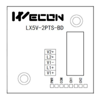
Wiring the PT100 sensors to the module is a key aspect of its usage. For 2-wire PT100 configurations, specific connections are required where V+ and L+ terminals are shorted, and the sensor leads are connected to L+ and VI-. In 3-wire PT100 configurations, two leads of the same color are connected to L+ and V+, while the third lead of a different color is connected to VI-. Adhering to these wiring instructions is critical for accurate sensor readings. It is also important to use appropriate cables (AWG25-16 is recommended) and ensure proper tightening torque for terminals (0.5Nm to 0.6Nm) to prevent poor contact or malfunctions. Signal cables should be kept separate from high-voltage power cables to avoid interference, maintaining a minimum distance of 100mm. Shielded wires should be properly grounded, but the ground point should not be the same as the high-voltage line.
Configuration of the module is primarily done through host computer software, such as Wecon PLC Editor2 (versions 2.1.204 and above). Users can access the "BD Module Configuration" interface to set various parameters. This includes defining the response time, which dictates the interval at which the PLC acquires data from the BD module (ranging from 0.1ms to 3276.7ms). Within the PTS configuration, users can enable/disable channels, confirm sensor type, adjust filtering intensity, set temperature overrun limits, and apply temperature calibration (gain and offset).
The module's integration with the PLC is managed through I/O mapping, where the temperature data from CH1 and CH2 are typically mapped to R devices (registers) within the PLC. This allows the PLC program to easily access and utilize the temperature values for control logic. After configuring the module parameters and I/O mapping, the settings are downloaded to the PLC, and the system is set to RUN mode for the changes to take effect.
Programming examples demonstrate how to interact with the module from the PLC. This can involve simple ladder logic to enable channels, read temperature values from the mapped registers, and write digital values for control purposes. The flexibility in configuration and programming allows the LX5V-2PTS-BD to be adapted to a wide range of temperature monitoring and control applications.
The LX5V-2PTS-BD BD Module is designed for reliable operation with minimal maintenance requirements. However, certain features and practices contribute to its long-term stability and ease of troubleshooting.
The comprehensive monitoring interface within the host computer software is a key maintenance feature. It allows users to continuously monitor the module's communication status and access detailed error information. This includes specific error codes for each channel, indicating issues such as temperature values exceeding the configured range. The ability to view these details in real-time helps in quickly identifying and diagnosing problems, reducing downtime.
The module's buffer memory (BFM) provides extensive diagnostic information. This includes not only channel-specific data like enable status, sensor type, filter intensity, and current value, but also communication-related parameters. These communication parameters include the current maximum package length, number of retransmissions (both general and subpackages), received and sent times of sync frames, control of transmissions and receptions, number of subscriptions sent and received, latest error code (which can be cleared by writing 0), number of bytes sent and received (both total and valid), and the total communication time since the module was powered on. This wealth of information is invaluable for diagnosing complex communication issues or network-related problems.
Regular checks of the module's LED indicators (PWR, COM, CH1, CH2) provide immediate visual feedback on its status. The PWR LED indicates power-on and program execution. The COM LED flashes during normal PLC communication and turns off during timeout, signaling communication problems. The CH1 and CH2 LEDs indicate the status of each channel: always on when the temperature is within range, flashing when outside the range, and off when the channel is closed. These indicators offer a quick and easy way to assess the module's health without needing to access the software interface.
Proper installation and wiring practices, as outlined in the manual, are crucial for preventing malfunctions and extending the module's lifespan. This includes ensuring firm installation, correct tightening torque for screws and terminals, and maintaining adequate separation between signal and power cables. Adhering to these guidelines minimizes the risk of poor contact, electrical interference, and physical damage.
The calibration feature, while primarily for accuracy, can also be considered a maintenance tool. Over time, sensor drift or environmental changes might necessitate recalibration to maintain measurement precision. The ability to adjust gain and offset values allows users to correct for these variations, ensuring the module continues to provide accurate temperature data throughout its operational life.
In summary, the LX5V-2PTS-BD BD Module is a robust solution for PT100 thermal resistance input, offering flexible configuration, precise temperature measurement, and comprehensive diagnostic capabilities. Its design emphasizes ease of installation, user-friendly configuration, and detailed monitoring, all contributing to reliable performance and simplified maintenance in industrial automation environments.
| Series | LX5V |
|---|---|
| Input Points | 2 |
| Communication Interface | RS485 |
| Communication Ports | RS485 |
| Power Supply | 24V DC |
| Operating Temperature | 0°C to 50°C |