2 iPump Quick Start Guide
800009-02 Rev.B
3
33
3 Connect
ConnectConnect
Connect
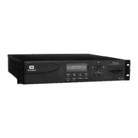
the following items (refer to Figures 1 and 2):
a)
L-band output from your antenna's LNB to the iPump's RF
input port (
a
aa
a
) [950 to 2150 MHz; female Type F connector
with extender cable attached or BNC connector if your unit
has the optional ASI input]
b)
a suitable monitor to the iPump's audio port (
b1
b1b1
b1
). (An
optional, auxiliary audio port (
b2
b2b2
b2
) is also available. See the
iPump User's Reference Manual for details.) [a 1/8-inch
stereo output jack is the connector for each audio port, but a
1/8-to-RCA adapter is included in the accessories bag]
c)
your monitor to the iPump's video (
c
cc
c
) port [
c
cc
c
is a female,
4-pin mini DIN (S-video) connector except in units with
optional decoders having a female, BNC connector. An
SVD-to-RCA adapter is included in the accessories bag.]
NOTE: Repeat steps b) & c) for the second decoder if
your iPump is equipped with two decoders.
d)
Your LAN line to the iPump's Ethernet port (
d
dd
d
)
[10/100baseT; female RJ-45 connector]
Figure 1. iPump Rear-panel Connectors
The Alarm port (
e
, Figure 1) on the rear panel may be used to
provide a contact closure during alarm conditions or on
command from Compel. See the iPump Reference Manual for
complete connector and signal details.