Installation of connector with pneumatic coupling (Pos� 4) and control - / bleeding
valve (Pos� 3)
Î
Insert the connector, according to the design, into the test piece as described on
Page 19 and Page 20.
Note: Ensure that the connector is securely plugged into the test piece using a
mechanical connection before proceeding.
Î
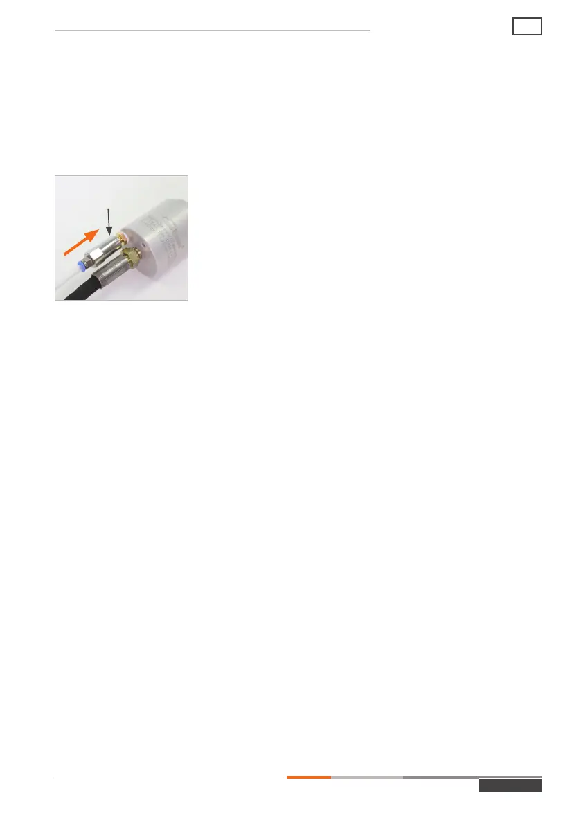
Plug the pneumatic coupling (Pos. 4) onto the control - /
bleeding valve (Pos. 3) and keep the coupling plugged in
(Figure 5). When the pneumatic coupling is plugged in, a
short pressure pulse is applied to the control - / bleeding
valve. The elastic front seals (Pos. 7) or main seals (Pos. 8)
are compressed and the connector creates a pressure-tight
connection.
Note: Regulate the pilot pressure to the minimum required
for sealing under test conditions (pressure or vacuum). This
extends the service life of the seals.
Î
Pull off the pneumatic coupling (Pos. 4) again. The integrated shut-off valve in the
pneumatic coupling prevents pilot pressure air from escaping.
The check valve in the control - / bleeding valve (Pos. 3) locks the pilot pressure in the
connector and the connector remains adapted.
- The connector is now connected pressure-tight to the test piece.
Î
To start the testing procedure, apply pressure to media inlet ‘B1’.
Figure 5
Pneumatic coupling
MD-10187-L51-R1.3.0-03
Page 23
Operating instructions
AE