Parameter Specifications
Input DC 10~15V, 300mA max standby 50mA.Power
Consumption 5.0 Watts max standby 0.6 watts.
Impulse Output Multi pulse (normal “High” level)
Inhibit Input High enable( +3v~+15v)
Signals
Out1~6 Output 1 pulse/coin
Con2 Input/output 4 pin male Extend connect port
Con3 Input/output 09FCS 5 pin male General I/O port
Connector
Con5 Input/output 09UCS 6 pin male General I/O port
User controls 5-ch
dip-switch
Sw1, sw2, sw3 for channel or impulse ratio select.
Sw4, sw5 for mode and other function select.
Overall Dimension
(HXWXD)
HI-09UCS: 102x99x55 mm
HI-09FCS: 124.5x120.5x64.5 mm
Speed of acceptable Max. 3 coins/second.
Diameter 18mm~30mm
Position 1.8 2.2 2.6 3
Coin size
(mm)
Thickness
Adjust
Thickness Range 1.2~2.0 1.2~2.4 1.2~2.8 1.2~3.0
Working temperature 5° ~50°
Weight HI-09UCS: 240g
HI-09FCS: 300g
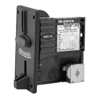
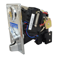
HI-09UCS / HI-09FCS
NE
W
(Drop inserting type)
(Front inserting type)
Feature
*Support 8 channels (coins) self-programming without PC.
*With an inhibit wire for game board.
*With 6 ch. Parallel output for each channel (coin) control.
*Support one coin then multi pulse output (impulse out ratio).
*With narrow or wide impulse width select (100ms and 50ms).
*Adjustable 4 kinds of coin thickness.
Specifications:
Operation mode: Before switching on the dc power,
Set DIP 4,DIP 5 to the "OFF" position.
Impulse and channel ratio table (500)
Record mode: Before switching on the dc
power, set DIP 4, DIP 5 to the "ON"
position.
HUAI I ELECTRONICS CO.,LTD
1
3
5
7
9
2
4
6
8
10
1. GND
2. +12V
3. Output ch5
4. Output ch6
5. Impulse output
6. Inhibit control
7. Output ch1
8. Output ch2
9. Output ch3
10. Output ch4
Accessory
HI-09UCS or HI-09FCS X1
Control board (pcb-09-2) X1
10p Signal cable X1
User manual X1
Screw bag (HI-09FCS only) X1
5P (09F) or 6P (09U) Signal wire X 1
Installation
Case 1:
Using 10p signal cable connect HI-09UCS/HI-09FCS
to control board (pcb-09-2). And need 4 wires connect
control board (pcb-09-2) to game board.
The 4 wires define as below:
1. +12V: for dc power (12 volt).
2. GND: for dc power (ground).
3. IMPULSE: for credit signal (output signal).
4. INHIBIT: control by game board for enable
or disable coin selector (input).
Case 2:
Using 5P or 6P signal wire connect to HI-09UCS/HI-09FCS
another end connect to game board and meter.
+12V
GND
Impulse
Inhibit
DIP SW "X" means off , "O" means on
Please make sure direction
The 5P wire define as below (HI-09FCS only)
1. +12V
2. Counter (Meter)
3. GND
4. Impulse (Credit)
5. Inhibit
The 6P wire define as below (HI-09UCS only)
1. GND
2. +12V
3. +12V
4. Counter (Meter)
5. Impulse (Credit)
6. Inhibit
1
2
3
4
5
6
1
2
3
4
5
Multi coin mode Out
DIP3, DIP2, DIP1 XXX XXO XOX XOO OXX OXO OOX OOO
Impulse out Ratio Impulse out Ratio (bonus) Ratio
Channel
1 2 3 4 5 6 7 8
1 XXX 1/2 1/4 1 1 1/2 1/2 1/2 1/4 1
2 XXO 1 1/2 1 1 1 1 1 1/2 2
3 XOX 50C 1 1/2 2 2 1 3 2 1+1/2 3
4 XOO 1$ 2 1 4 2 2 5+1 4+1 2+1 4
5 OXX 2$ 4 2 8 4 4+1 10+2 5+1 4+2 5
6 OXO 5 2 8 4 NA NA 8+2 5+2 6
7 OOX 8 4 10 10 NA NA 10+2 NA 6
8 OOO 10 5 10 10 NA NA NA NA 6