Operation and Maintenance Manual for WP2.1C/WP3.9C Series Marine Diesel
9
fracture of the engine.
Section
Ⅲ
Engine
Assembly
and
Disassembly
3.1 Cylinder Head
The monolithic cylinder head is made of high strength cast iron. The fuel
injectors and valve train parts are mounted on the cylinder head.
The cylinder head assembly is composed mainly of cylinder head, fuel injectors,
valve mechanism, intake and exhaust manifolds, front cover plate, rear cover plate,
thermostat and water temperature sensor.
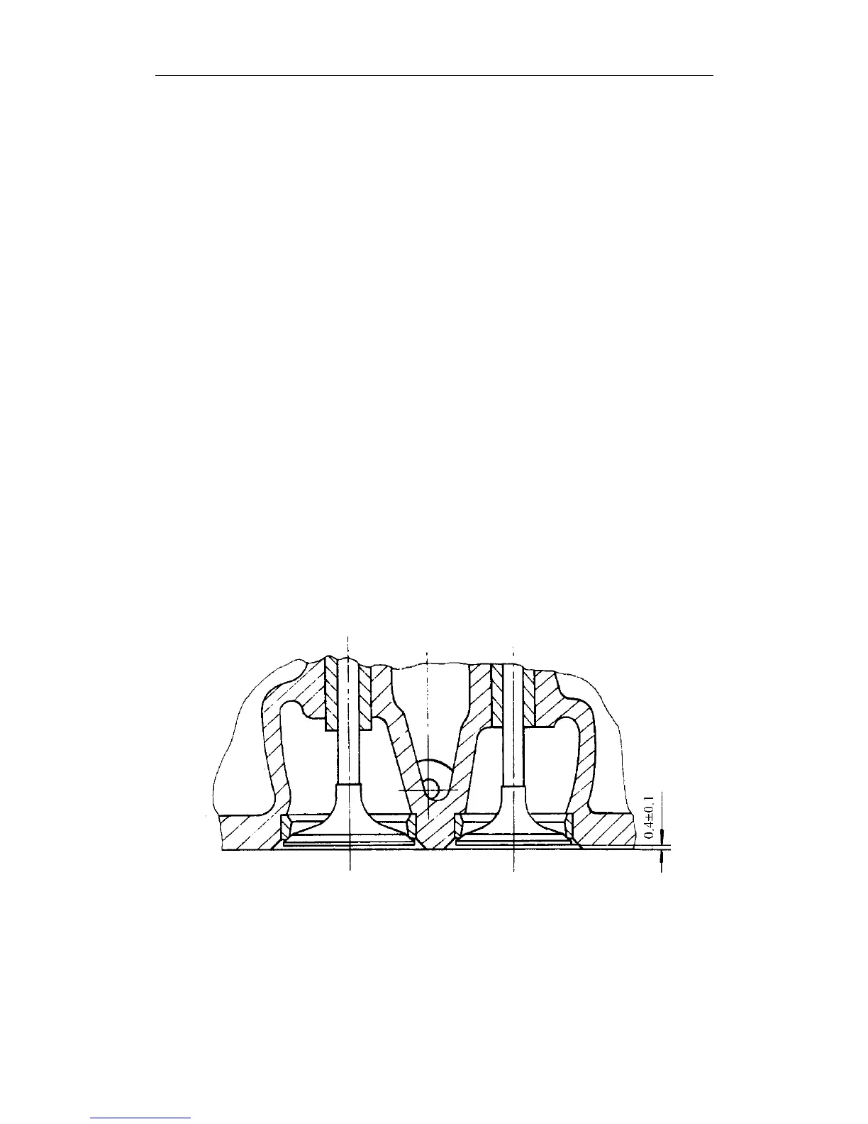
The inlet and exhaust valve guides are of the same design. The valve guide and
valve seat insert are press-fitted into the cylinder head. The valves are not
interchangeable because they and their seats have been lapped in pairs to form
continuous, regular and bright seating lines. No leakage is allowed in the seat line
of the valve. The normal valve seating line width is 1.0~1.4mm. If it gets too wide to
ensure tight sealing, reshape it by means of a special reamer. Each valve is marked
with a cylinder number, because they are not interchangeable in assembly. The
standard valve recession, i.e. the specified distance from the valve head to the cylinder
head surface is 0.4±0.1mm (see Fig.1). If the valve recession is too small, ream the
valve insert to enlarge it; if it is too large, replace the valve and valve seat.
Fig.1
The cylinder head is mounted on the cylinder block with 18 bolts. They should
be evenly tightened in 2~3 steps . The tightening of the bolts in each step should