Operation and Maintenance Manual for WP2.1C/WP3.9C Series Marine Diesel
13
The difference in weight between the piston-connecting assemblies for the same
engine should be less than 10 grammes. This requirement can be met through
selection.
The crankshaft is made of ductile nodular cast iron. There are five main journals
and four crankpins on the crankshaft. An oil hole in each journal leading to the
neighboring crankpin is employed to supply lubricating oil to the crankpin bearing.
On the front end of the crankshaft, there are the timing gear and oil pump driving gear,
both driven with a flat key. On the front and rear of the crankshaft, there are oil seals
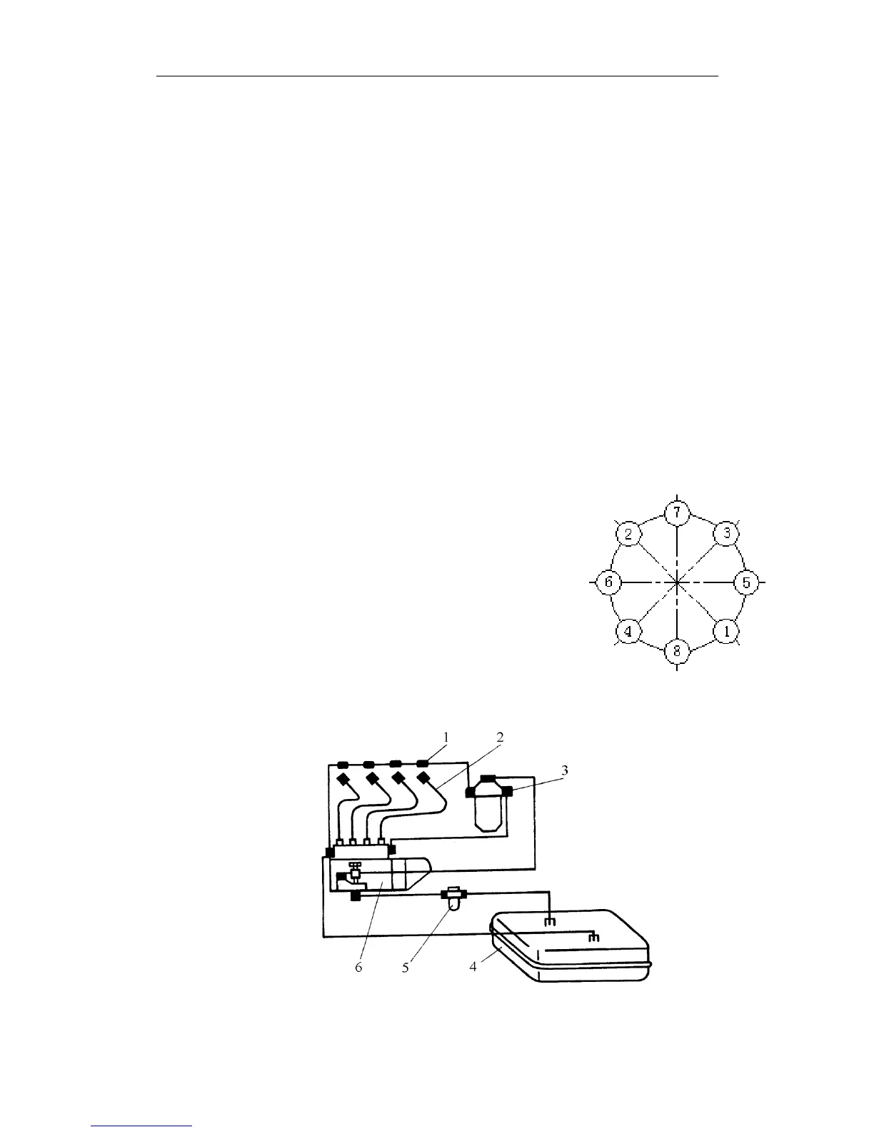
to prevent oil leakage. When installing the flywheel, tighten the flywheel bolts evenly
in the order shown in Fig.6 to reach the specified torque in 2~3 steps. The crankshaft
and flywheel are dynamically balanced as an assembly. The same figure is marked
side by side on the crankshaft flange end and the flywheel as an indication of the
pairing relation and mounting position. Be sure to assemble the flywheel with the
crankshaft in the correct position as indicated with the figure mark.
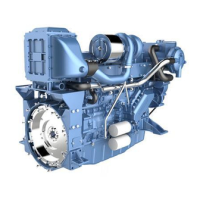
3.5 Fuel Supply System
The fuel supply system consists of the fuel tank, rough
filter, feed pump, fine filter, injection pump, governor, injectors
and fuel pipelines.Fuel from the fuel tank flows through the
strainer into the feed pump and then pass through the fuel filter
to the injection pump. The fuel at high pressure from the
injection pump is delivered to the fuel injector and sprayed into
the combustion chamber. The superfluous fuel from the
injection pump and injectors flows back to the fuel tank.(see
Fig.7)。 Fig. 6
1. Fuel return pipe 2. Fuel injection pipe 3. Fuel fine
4. Fuel tank 5. fuel rough filter 6. Filter
Fig. 7