Do you have a question about the Weider Victory Club Series 320 and is the answer not in the manual?
| Brand | Weider |
|---|---|
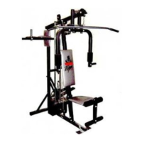
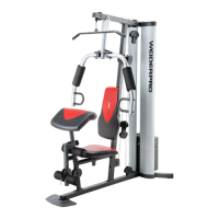
| Model | Victory Club Series 320 |
| Category | Fitness Equipment |
| Language | English |
Read instructions, use as described, ensure level surface, and inspect parts regularly.
Always hold handles, keep hands from moving parts, keep children away, and wear appropriate attire.
Consult a physician before starting any exercise program, especially for those over 35 or with health issues.
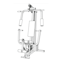
Manual covers assembly, adjustments, use, maintenance tips, and parts information.
Provides estimated assembly time and lists required tools for setup.
Scale guide for 3/8" Hex Head Bolts, Carriage Bolts, or Round Head Screws.
Scale guide for 5/16" Hex Head Bolts, Carriage Bolts, and Round Head Screws.
Illustrations of flat washers and nylon lock nuts used in assembly.
Illustrations of Round and Square Plastic Caps for finishing.
Instructions for attaching the Seat (6) to the Sliding Seat Adjuster (8) using bolts and washers.
Instructions for attaching the Backrest (4) to the Sliding Seat Adjuster (8) using bolts and washers.
Orient Main Frame (2) and slide Seat Adjuster (8) with Seat (6) onto the main frame.
Assemble Thumb Screw (56) into the Welded Nut to secure the seat assembly.
Press 2" Square Plastic Insert Caps into the feet of the Upright (1) and Front Support (3).
Assemble Front Support (3) to the bottom of the Main Frame (2) using bolts and nuts.
Attach Main Frame (2) to the lower and upper Cross-Members of the Upright (1) using hardware.
Press 1 3/4" Square Plastic Insert Caps into the Leg Curl (10) tubing and adjuster.
Assemble Weight Pin (15) through Leg Curl (10) and slide Weight Stop (63) onto the pin.
Apply detergent to Pad Bars (7) and slide on Foam Rollers (9).
Assemble Leg Curl (10) into the Welded Brackets of the Leg Curl Adjuster (11) using hardware.
Slide Leg Curl Adjuster (11) into Main Frame (2) leg and secure with Locking Pin (70).
Install Plastic Caps and Foam Grips onto the Handles of Adjustable Uprights (12).
Slide Adjustable Uprights (12) into Main Uprights (1) and set height with Locking Pin (70).
Place Backrest Bar (14) into Welded Brackets on Upright (1) to incline Backrest (4).
Align holes in Sliding Seat Adjuster (8) with Main Frame (2) and lock with 'L' Pin (71) and Spring Clip (57).
Adjust Seat (6) up or down by pinning through the Seat Bracket with 'L' Pin (71) and Spring Clip (57).
Adjust Backrest (4) to horizontal position or inclined position using Backrest Bar (14).
Warrants equipment free from defects for 90 days and frame for three years from purchase.
Disclaims implied warranties and consequential damages; lists exclusions like misuse.
Procedure to write to Parts Service with details and proof of purchase for warranty claims.
Contact information for Parts Service: phone number and address for inquiries and repairs.