10
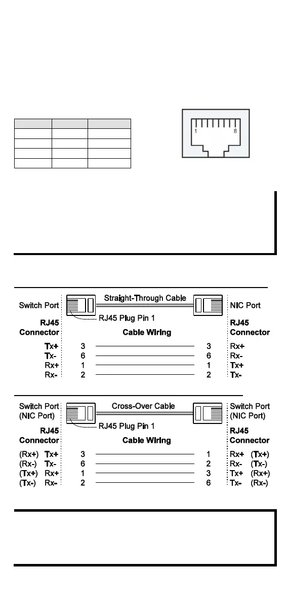
PoE 10/100BaseT(X) Ethernet Port Connection
PoE 10/100BaseT(X) ports located on the switch’s front panel are used
to connect to PoE-enabled devices. The pinout follows the “Alternative
A, MDI-X mode” of 802.3af/at standards. Please see the details in the
following table.
According to IEEE 802.3af/at standards, the PD shall be
implemented to be insensitive to the polarity of the power
supply and shall be able to operate per MDI mode and MDI-X
mode. However, some PDs only support MDI mode or MDI-X
mode only. The following figure shows how to select the correct
cable between the PD and IE-SW-BL06-4PoE switch.
RJ45 (8-pin) to RJ45 (8-pin) Straight-Through Cable Wiring
RJ45 (8-pin) to RJ45 (8-pin) Cross-Over Cable Wiring
If the PD only supports MDI mode (V+, V+, V-, V- for pins 1, 2,
3, 6), choose a cross-over Ethernet cable to connect the PD and
the switch. If the PD only supports MDI-X mode (V-, V-, V+, V+
for pins 1, 2, 3, 6), choose a straight-through Ethernet cable
between the PD and the IE-SW-BL06-4PoE switch.
 Loading...