12
ATTENTION
To actively update DIP switch settings, power off and then
power on the Ethernet Switch.
LED Indicators
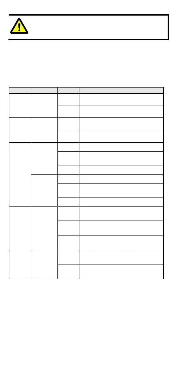
The front panel of the Ethernet Switch contains several LED indicators.
The function of each LED is described in the following table.
Power is being supplied to power
input P1.
Power is not being supplied to
power input P1.
Power is being supplied to power
input P2.
Power is not being supplied to
power input P2.
TP port’s 10 Mbps link is active.
Data is being transmitted at 10
Mbps.
TP Port’s 10 Mbps link is inactive.
TP port’s 100 Mbps link is active.
Data is being transmitted at 100
Mbps.
TP Port’s 100 Mbps link is inactive.
FX port’s 100 Mbps link is active.
Data is being transmitted at 100
Mbps.
FX Port’s 100 Mbps link is inactive.
Power is being supplied to Powered
Device (PD)
Power is not being supplied to
Powered Device (PD)
Auto MDI/MDI-X Connection
The Auto MDI/MDI-X function allows users to connect the Ethernet
Switch 10/100BaseTX ports to any kind of Ethernet device, without
needing to pay attention to the type of Ethernet cable being used for the
connection. This means that you can use either a straight-through cable
or cross-over cable to connect the Ethernet Switch to Ethernet devices.
 Loading...