1 2 3
Hardware Installation Guide
Unmanaged Fast Ethernet Switches
IE-SW-EL05-5TX (Part No. 2682130000)
IE-SW-EL08-8TX (Part No. 2682140000)
1. Introduction
Ethernet Switches from Weidmüller are designed with a very compact housing size and
are fitted with a robust housing. To ensure reliable, error-free operation, and to prevent
damage or injury, please read the operating instructions, all safety information provided
in this document and any other safety information that were supplied with the product.
2. Safety notice
Switch off the electrical power before removing the power connection!
The device heats up during operation. Allow the unit to cool down or use
protection gloves when carrying out any work.
The device may only be connected to the supply voltage shown on the
product label. Higher voltage than specified will destroy the device.
The device must be supplied by a SELV source as defined in the Low
Voltage Directive 2014/35/EU and 2014/30/EU.
Installation, commissioning and maintenance may only be performed by
qualified electricians.
Observe the operating instructions.
Indoor use and pollution degree II, it must be wiped with a dry cloth for
clean up the device and label.
o Utilisation en intérieur et degré de pollution II, il faut l'essuyer avec un
chiffon sec pour nettoyer l'appareil et son étiquette.
Do not block air ventilation holes.
o Ne bouchez pas les orifices de ventilation.
If the equipment is used in a manner not specified by the manufacturer,
the protection provided by the equipment may be impaired.
o Si l’appareil est utilise d’une maniere non specifiee par le fabricant, la
protection qu’il apporte peut se voir diminuee.
Shall be mounted in the Industrial Control Panel and ambient
temperature is not exceed 75 degrees C.
o Doit être monté dans le panneau de commande industriel et la
température ambiante ne doit pas dépasser 75 degrés C.
Intended use
The device is intended for the realization of communication networks within an industrial
environment, it is intended to be used in a restricted access location. The device may only be
used within the scope of the specified technical data. The device is intended to be mounted to
a well-grounded mounting surface, such as a metal panel. Any other use may result in
unintentional malfunction and damage. Observing the documentation is part of the intended
use.
Environmental conditions
This equipment is intended to be used in a restricted access location.
When planning the installation site make sure that the ambient temperature during operation
will not exceed the temperature given in the technical data.
Also make sure that the air flow will not be compromised by other devices.
Ensure that the mounted and wired device is not exposed to any mechanical stress.
FCC compliance
This device complies with part 15 of FCC Rules. Operation is subject to the following two
conditions: (1) This device may not cause harmful interference, and (2) this device must accept
any interference received, including interference that may cause undesired operation.
3. Package Checklist
Your Ethernet Switch is shipped with the following items:
Ethernet Switch
Hardware Installation Guide (printed)
4-Pin Terminal connector
Protective caps for RJ45 ports
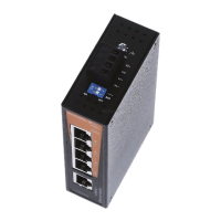
4. Panel Layouts
1. Terminal block for power input
PWR1/PWR2
2. Grounding screw / Frame ground
Note: The shielding ground of the LAN
port is electrically connected to the
grounding screw.
3. Power input LEDs (PWR1 / PWR2)
4. LAN port Link/Activity LED
5. LAN port 10/100 Mbps LED
6. 5/8 x 10/100BaseT(X) ports
7. Article Number
8. Screw holes for wall mounting kit
9. DIN-Rail kit
5. Mounting Dimensions
IE-SW-EL05-5TX (units = mm)
IE-SW-EL08-8TX (units = mm)
6. DIN-Rail Mounting
Slide the switch onto a DIN-rail and make sure that the switch’s Din-rail clip clicks into
the rail firmly.
STEP 1: Insert the top of the
DIN-Rail into the slot just below
the stiff metal spring.
STEP 2: The DIN-Rail
attachment unit will snap into
place as shown below.
To remove the DIN-rail from the Ethernet Switch, simply reverse Steps 1 and 2.