M
Micheal MyersAug 3, 2025
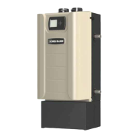
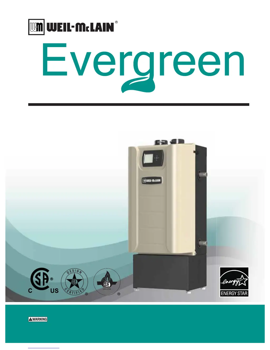
Why Weil-McLain Evergreen EVG 110 Boiler display screen is blank and unresponsive to heat requests?
- CChristopher NavarroAug 3, 2025
If the Weil-McLain boiler's display screen is blank and it's not responding to calls for heat, there could be several reasons: * The control might not be getting 24V power. Check the wiring for any short circuits or incorrect connections. * The 3-amp low voltage fuse on the control could be blown. Inspect the fuse (page 108). * The transformer connection to the control might be faulty. Verify the connection, referring to the wiring diagram, and check for a 24V output from the transformer.