WP8024ADAM User’s Manual V1.42
4.2
、
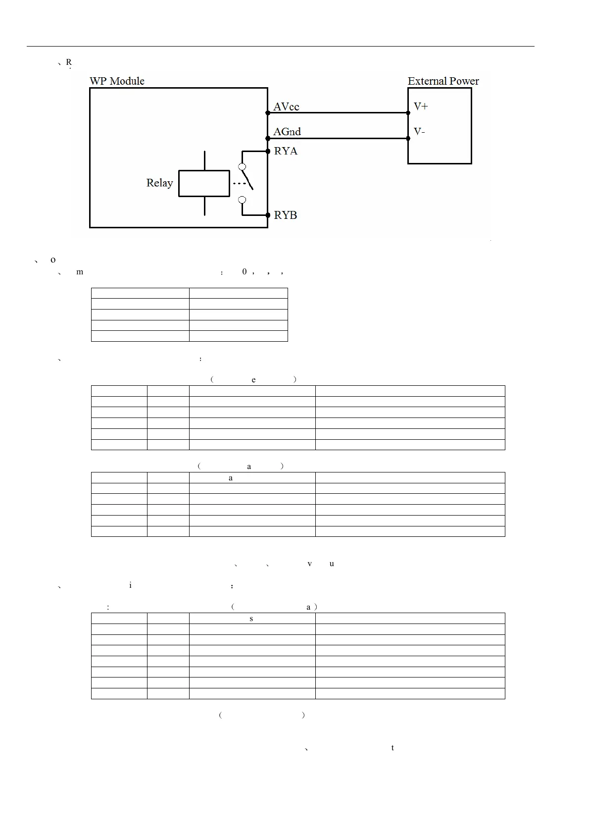
Relay output
5
、
Communication Instruction
5.1
、
Communication parameter (default setting)
:
9600
,
N
,
8
,
1
Parameter Description
9600 baud rate
N(no check) check bit
8 data bit
1 stop bit
5.2
、
Command for digital input collection
:
Send: 01 02 00 00 00 08 79 CC
(
example/hexadecimal
)
data byte data description remark
01 1 module address Address range 01-FE
02 1 function code 02-read input bit
0000 2 input address(1x mode) 0000-initial address of input bit
0008 2 read length of input bit 0008-read 8 input bits
79CC 2 CRC check code CRC check code for all data
Receive: 01 02 01 C2 20 19
(
example/hexadecimal
)
data byte data description remark
01 1 module address Address range 01-FE
02 1 function code 02-read input bit
01 1 byte numbers 01-read one byte length
C2 1 read data C2-read input bit status
2019 2 CRC check code CRC check code for all data
Converting reading data “C2” to 2 hexadecimal results “11000010”. From left to right, it represents the 8 digital input channel
status DI_08 ~ DI_01. Here it means DI_08
、
DI_07
、
DI_02 have input but others no.
5.3
、
Command for digital output (several controls)
:
Send: 01 0F 00 00 00 04 01 03 7E 97
(
example/hexadecimal
)
data
byte
data description
remark
01
1
module address
address range:01-FE
0F
1
function code
0F-write multiple coil
0000
2
coil address(0x mode)
0000-initial address of coil
0004
2
write coil length
0004-write 4 coils
01
1
write data byte
01-write one byte data
03
1
write data
03-write 4 coil’s output status
7E97
2
CRC check code
CRC check code for all data
Receive: 01 0F 00 00 00 04 54 08
(
example/hexadecimal
)
Converting reading data “03” to 2 hexadecimal results “00000011”,last 4 numbers are active. From left to right, it represents
the 4 relay output channel status RY4-RY1. Here it means RY2
、
RY1 have output but others no. When module receives correct
command, it will make corresponding actions and send response back to the master. This is successful communication.