5. Using the Phillips-head screwdriver, as well as something to hold the nut shown in Figure 4 above
(pliers, socket, adjustable wrench, etc.), loosen and remove the nut, then remove the grounding wire
and bolt. Do not drop the washers. If you do drop them, retrieve them from the grating, or turn the unit
over. If need be, remove the inner and outer filter. This will let you retrieve the washers from the
bottom.
6. Set the front panel assembly face-down on the work surface, making sure the power cord is not bent
where it meets the front panel. Let it hang off the work surface.
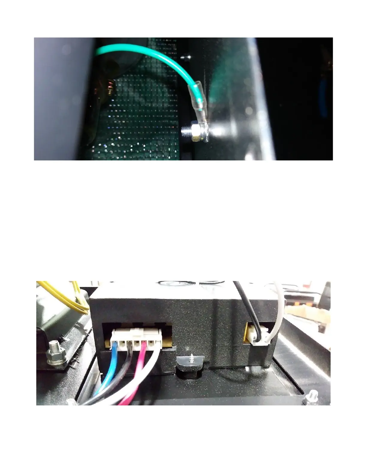
7. Check the wiring connections to the PCB, as shown in Figure 5 below. If they do not match what is
shown in Figure 5 below, correct them.
Figure 4: Inside of grounding bolt.
Figure 5: Wired connections to PCB. From left to right: blue, black, red, and white go in slots 1, 3, 5,
and 7 (respectively) of the 4-wire connector shown on the left. The black and white wires go in slots 1
and 3 (respectively) of the 2-wire connector shown on the right.
 Loading...