CLEANING
1. Unplug the power supply before cleaning. Clean the exterior of the tool with a damp cloth and a mild cleanser.
Never immerse the machine in water or other liquids. Do not at any time let brake fluids, gasoline, petroleum-based
products, penetrating oils, etc., come in contact with plastic parts. Chemicals can damage, weaken or destroy plas-
tic which may result in serious personal injury.
2. Ensure that the ventilation slots are not blocked to prevent overheating. Blow out any dust and debris using clean,
compressed air. Always wear eye protection when using compressed air.
3. Regularly clean the underside of the chain cover, tension mechanism, and chain pinion using clean compressed
air or a brush. Always wear eye protection when using compressed air.
4. Keep handles free from oil and grease to ensure a secure hold.
14
MAINTENANCE
WARNING! To avoid injury from accidental startups, be sure that the tool is switched off and disconnected
from the power supply before inspecting the tool, making adjustments or changing accessories.
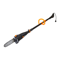
Fig. 7
1
2
REPLACING THE GUIDE BAR AND SAW CHAIN
The guide bar must be replaced if the groove of the guide is
worn out or the spur wheel in the guide bar is damaged or worn
out. The saw chain must be replaced when it becomes dull. Re-
placement guide bars (part no. 4019-117) and saw chains (part
no. 4019-118) can be ordered from wenproducts.com.
1. Disconnect the tool from the power source.
2. Fully loosen chain tensioning wheel (outer wheel) by turning
it counterclockwise (Fig. 7 - 1). Make sure to turn it all the way;
this will allow the chain cover to be properly placed back later.
3. Fully loosen cover lock knob (inner knob) by turning it coun-
terclockwise (Fig. 7 - 2). Remove cover lock and chain cover.
4. Remove the bar and chain. Replace the worn bar and chain
as necessary. Place the saw chain into the groove of the outside
edge of the guide bar.
NOTE: The chain’s direction must match the indication shown
on the inside housing or in Fig. 8.
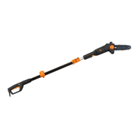
Fig. 8
5. Place the guide bar and chain onto the bar mount (Fig. 8). Guide the chain around the drive pinion.
6. Check the position of the tensioner pin on the underside of the chain cover. Ensure that the tensioner pin drops
into the hole on the bar when re-installing the chain cover. Make sure the cover clicks in place. Insert the chain cover
lock knob, but do not tighten it all the way.
7. Adjust the chain tension by rotating the tension adjustment wheel (outer wheel). Clockwise rotation increases the
chain tension; counterclockwise rotation reduces the chain tension. The saw chain is correctly tensioned if the chain
can be lifted about 2mm (1/16”) from the center of the guide bar. Fully tighten the chain cover lock knob.
NOTE: The saw chain must be tensioned properly to ensure safe operation. Since the saw chain heats up during
operation, its length can therefore fluctuate. Check the chain tension every 10 minutes of operation and adjust as
necessary, particularly for new saw chains.
 Loading...