34
TOPITEC
®
TOUCH User Manual | 11-2020
6. OPERATION
Warning
The TOPITEC
®
Touch must only be operated by competent personnel (operating personnel)
who have been properly instructed in its operation.
Note
Before starting production, ensure that there are no objects
(e.g. tools, residual material, etc.) near the
TOPITEC
®
TOUCH mixing system.
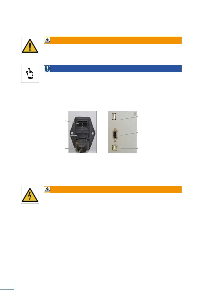
6.1 Connection to power supply, interfaces
The rear panel of the TOPITEC
®
TOUCH contains the following control devices and interfaces:
1. Main switch (power switch)
When this switch is ON, the TOPITEC
®
TOUCH is powered from the power mains.
Warning
If the main switch needs to be switched off for cleaning, maintenance or repair work,
always disconnect the power cable from the power socket
(to prevent inadvertent switching on).
2. Fuse holder (recessed)
containing 2 fuses (5 x 20 mm, 10 A T (slow-acting, sand-filled).
3. Power socket (3-pin)
with phases and PE conductor; socket for conventional IEC-60320 C13/C14 cable plug. The power cable
must be connected to a properly earthed power socket with a PE conductor.
4. USB interface for maintenance purposes
Interface connection for the TOPITEC
®
TOUCH data memory or technician.
5. Printer interface (RS 232, serial port)
The serial interface allows for the connection of an external printer for the printing of product labels or the
identification of dispensing jars.
6. PC interface (USB)
The USB port allows you to connect device to a PC or the apotec
®
connect.
USB interface for
maintenance purposes
Printer interface
(RS 232, serial port)
PC interface (USB)
Main switch
(power switch)
Fuse holder
(recessed)
Power cable socket
(3-pin)
1.
2.
3.
4.
5.
6.
Fig. 6-1 Power connection, interfaces
 Loading...