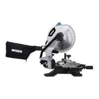
This document describes the WESCO WS7170 and WS7170U Compound Mitre Saws, providing detailed instructions for assembly, operation, and maintenance.
Function Description
The WESCO Compound Mitre Saw is a stationary power tool designed for making straight, longitudinal, and transversal cuts in wood and wood-like products. It supports horizontal mitre angles from -45° to +45° and vertical bevel angles from 0° to +45°. The saw is equipped with a dust extraction port for efficient sawdust collection, a work clamp for securing workpieces, and a LED light for improved visibility in dark or enclosed areas.
Important Technical Specifications
| Specification |
WS7170 |
WS7170U |
| Rated voltage |
220-240V~50/60Hz |
110-127V~50/60Hz |
| Rated Input power |
1800W |
1800W |
| No load speed |
5000/min |
5000/min |
| Bevel capacity |
0-45° Left |
0-45° Left |
| Blade size |
255mm |
255mm |
| Double insulation |
Class II |
Class II |
| Machine weight |
10.94kg |
10.94kg |
Cutting Capacity:
| Cut Type |
Capacity (mm) |
| Max cutting mitre/bevel 0°/45° |
140*40 |
| Max cutting mitre/bevel (R) 45°/45° |
95*40 |
| Max cutting mitre/bevel 0°/0° |
140*70 |
| Max cutting mitre/bevel 45°/0° |
95*70 |
Accessories:
The saw comes with the following accessories:
- Extension rail (2)
- Work clamp (1)
- Dust bag (1)
- TCT blade (1)
- Hex key (1)
Usage Features
- Dust Extraction: A dust bag can be clipped onto the dust extraction port on the upper blade guard to collect sawdust. The bag should be emptied when it is approximately 2/3 full to maintain optimal collection efficiency.
- Table Extension Rails: Extension rails can be inserted into holes on either or both sides of the base to support longer workpieces. They are secured by tightening a locking knob.
- Work Clamp: Workpieces should always be clamped using the provided work clamp (15) to ensure stability during cutting. The clamp's height and position can be adjusted using its respective knobs.
- Mounting: The mitre saw should be permanently mounted to a firm, stable workbench using four mounting bolts (not supplied) to prevent movement during operation.
- Saw Head Release: The saw head is locked in the down position for storage and transport. To release it, apply downward pressure on the saw arm and pull out the release knob (19). The head will then gently raise to the upper position.
- Mitre Angle Adjustment: The mitre table locking lever (8) is used to set the desired mitre angle. Loosen the mitre angle adjusting handle (9), depress the locking lever, move the handle to the desired position (0° to 45° left or right), release the lever, and re-tighten the handle. The mitre table has positive click stops at common angles (0°, 15°, 22.5°, 30°, and 45°).
- Bevel Angle Adjustment: The bevel lock (20) sets the blade at the desired bevel angle (0° to 45° to the left). Loosen the bevel lock, tilt the saw head to the left, and re-tighten the lock once the desired angle is reached. The work clamp (15) should be assembled on the right side when adjusting for bevel cuts.
- Spindle Lock: The spindle lock button (18) prevents the blade from rotating, facilitating blade installation, changing, or removal. It should be depressed and held during these operations.
- Starting and Stopping: To start the saw, push the lock-off lever (23) and then squeeze the trigger switch (22). To stop, release the trigger switch.
- Chop Cut: For a chop cut, position the material on the rotating mitre table (11), clamp it securely, and ensure the mitre table locking lever (8) and bevel lock (20) are tightened. Start the motor, allow the blade to reach maximum speed, then slowly lower the blade through the workpiece. Release the trigger and wait for the blade to stop completely before raising it.
- Bevel Cut: A bevel cut is made with the blade at an angle to the workpiece. Adjust the bevel angle as described above, then perform a chop cut.
- Mitre Cut: A mitre cut is made at 0° bevel and a mitre angle from 45° left to 45° right. Adjust the mitre angle as described, then perform a chop cut.
- Compound Cut: This cut combines a mitre angle and a bevel angle simultaneously, used for moldings, picture frames, and boxes with sloping sides. Adjust both angles as described, then perform a chop cut.
- LED Light: The integrated LED light can be turned on by pressing the LED light on/off switch (24) to the "I" position, and off by pressing it to the "OFF" position.
Maintenance Features
- General Maintenance: Always disconnect the saw from the power source before any adjustments, servicing, or maintenance. Ensure all keys, wrenches, screws, bolts, and other fittings are securely tightened after maintenance. Do not use water or chemical cleaners; wipe the tool clean with a dry cloth. Store the power tool in a dry place and keep ventilation slots and controls free of dust.
- Precision Angle Setting: Although factory-set, it is advisable to periodically check and adjust the 0° setting of the rotary table and the 90° perpendicular setting of the tilt. This involves using a try square (e, not supplied) to verify the angle between the straight guide and the blade, and adjusting locking screws (f) if necessary. Similarly, check the blade's angle relative to the rotary table and adjust the bevel lock (20) and adjustment screw (g) if needed.
- Changing the Saw Blade:
- Unplug the saw.
- Push down on the saw arm and pull out the release knob (19) to release the arm.
- Raise the saw arm to its full raised position.
- Rotate the lower blade guard counter-clockwise to expose the upper locking screw (h). Loosen this screw (do not unscrew completely).
- Press the spindle lock button (18) and rotate the blade bolt until the spindle locks.
- Use the hex key (12) to loosen and remove the blade bolt (turn clockwise to loosen). Do not remove the inner blade washer.
- Apply a drop of oil onto the inner and outer blade washers where they contact the blade.
- Always install the blade with the teeth and arrow pointing down at the front of the saw. The direction of blade rotation is also stamped on the lower blade guard.
- Ensure the inner blade washer is replaced before placing the blade on the spindle.
- Allow the motor to come to a complete stop before engaging the spindle lock to prevent damage. Ensure the spindle lock is disengaged before reconnecting to power.
- Replacing Carbon Brushes: Check carbon brushes regularly. If worn down to about 4mm, replace them with a new set (not supplied), always in pairs. Use a slotted screwdriver to turn the cap counter-clockwise, replace the brush, and ensure it is well-located and secured.
- Moving the Saw: When transporting, ensure the saw head is locked in the lower position, and the rotary table locking knob and bevel lock lever are securely tightened.