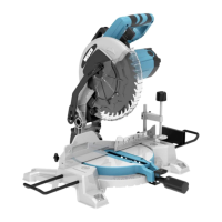
The WESCO WS7172 / WS7172U is a compound mitre saw designed for making straight lengthways and crossways cuts in wood and wood-like products. It is not intended for use with abrasive cut-off wheels for cutting ferrous materials such as bars, rods, or studs, as abrasive dust can jam moving parts and burn plastic components.
Function Description:
This stationary power tool is used for precise cutting of workpieces at various angles. It features a rotating mitre table for horizontal angle adjustments from -45° to 45° and a bevel lock for vertical inclination adjustments from 0° to 45° (left side only for bevel cuts). The saw head can be lowered and pushed through the workpiece to make cuts. A spindle lock button prevents the blade from rotating during blade changes. Dust extraction is facilitated by a dust bag that attaches to the dust extraction port, helping to maintain cutting efficiency and a cleaner work area. The saw is equipped with a work clamp to secure workpieces, and table extension rails are provided for supporting longer or wider materials.
Important Technical Specifications:
- Model: WS7172 (220-240V~50/60Hz) / WS7172U (110-127V~50/60Hz)
- Rated Input Power: 1800W
- No Load Speed: 5200/min
- Bevel Capacity: 0-45° Left
- Blade Size: 255mm
- Double Insulation: Yes (Class II)
- Machine Weight: 11.73 kg
Cutting Capacity:
- Max cutting mitre/bevel 0°/45°: 48*135mm
- Max cutting mitre/bevel (R) 45°/45°: 48*95mm
- Max cutting mitre/bevel 0°/90°: 70*140mm
- Max cutting mitre/bevel 45°/90°: 70*100mm
Usage Features:
- Carry Handle (Fig. A1, A2): For easy transportation, align and tighten the two bolts on top of the machine.
- Dust Extraction Port (Fig. B1, B2): Attach the provided dust bag to the port by depressing the metal ring clip. Empty the bag when it is approximately 2/3 full for optimal dust collection.
- Table Extension Rail (Fig. C1-C4): Install extension bars on both sides and a set plate on one side to support long workpieces. Loosen and tighten screws to secure.
- Work Clamp (Fig. D): Secure workpieces by inserting the clamp into the hole at the rear of the fence. The adjustment knob (a) controls rail height (c), and the clamp lock knob (b) secures the clamp.
- Mounting Bolt (Fig. E): Permanently mount the saw to a firm, stable workbench using appropriate machine bolts, lock washers, and hex nuts through the four mounting holes in the saw base.
- Release Knob (Fig. F1-F3): To release the saw head from its locked-down position, apply downward pressure on the saw arm and pull out the release knob. The saw head will gently rise.
- Mitre Table Locks (Fig. G1, G2): Adjust the mitre angle (0° to 45° left or right) by loosening the mitre angle adjusting handle, moving the table to the desired position, and then re-tightening. Positive click stops are available at 0°, 15°, 22.5°, 30°, and 45°.
- Bevel Lock (Fig. H1-H4): Adjust the bevel angle (0° to 45° to the right) by loosening the bevel lock knob, moving the saw head, and then re-tightening. The extended fence for bevel cutting needs to be pulled outwards and re-locked.
- Spindle Lock Button (Fig. I): Depress and hold this button to prevent blade rotation during blade installation or removal.
- Starting the Saw (Fig. J): Push the lower blade lock lever outwards, press down the saw head, squeeze the on/off switch, and allow the blade to reach full speed before cutting. Release the switch and wait for the blade to stop completely before raising the saw head.
- Cutting Repetitive Lengths (Fig. C3): Use the set plate on the extension bar to facilitate cutting multiple pieces to the same length.
- Cross Cut (Fig. K): Make a 90° crosscut with the mitre table set at 0°. Ensure the workpiece is clamped and the mitre table locking lever and bevel lock are tightened.
- Bevel Cut (Fig. L): Perform a bevel cut at 0° mitre and any bevel angle from 0° to 45° left.
- Mitre Cut (Fig. M): Execute a mitre cut at 0° bevel and any mitre angle from 0° to 45° left or right.
- Compound Cut (Fig. N): Make cuts using both a mitre angle and a bevel angle simultaneously, often for moldings or picture frames. Always perform a test cut on scrap wood first.
Maintenance Features:
- General Maintenance: Always disconnect the power tool from the power source before any adjustments, servicing, or maintenance. Ensure all keys, wrenches, screws, bolts, and fittings are securely tightened after maintenance. Do not use water or chemical cleaners; wipe clean with a dry cloth. Store in a dry place. Keep motor ventilation slots and working controls free of dust.
- Precision Setting of Angles (Fig. O1-O4): Periodically check and adjust the 0° setting of the rotary table and the 90° perpendicular setting of the tilt. Use a try square to verify the 90° angle between the straight guide and the blade. Adjust locking screws (e) for the straight guide and adjustment screws (f, g) for the bevel scale as needed.
- Changing the Saw Blade (Fig. P1-P4): Unplug the saw. Push down the saw arm and pull out the release knob. Raise the saw arm. Push the lower blade lock lever outwards and rotate the lower blade guard counter-clockwise to expose the upper locking screw (h). Loosen screw (h) but do not remove it completely. Press the spindle lock button and rotate the blade bolt until it locks. Use the wrench to loosen the blade bolt (clockwise to loosen). Do not remove the inner blade washer; wipe a drop of oil onto both inner and outer blade washers. Install the new blade with teeth and arrow pointing downwards at the front of the saw. Ensure the inner flange sits behind the saw blade. Reposition the outer flange, depress the spindle lock button, reposition the blade bolt, and tighten securely (anti-clockwise to tighten). Re-tighten locking screw (h). Check blade guard operation.
- Replacing Carbon Brushes (Fig. Q): Regularly check carbon brushes. If worn down to about 4mm, replace them in pairs with a new set. Use a slotted screwdriver to turn the cap counter-clockwise to release the brush, then replace and secure it.
- Moving the Saw: When transporting, ensure the saw head is locked in the lower position, and the rotary table locking knob and bevel lock lever are securely tightened.