EasyManua.ls Logo

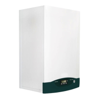
Westen boyler digit User Manual

Westen boyler digit
180 pages
To Next Page IconTo Next Page
Page #1 background imageLoading...
Page #1 background image
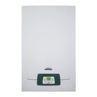
High performance gas-red wall-mounted boilers with rapid storage boiler
instructions manual for users and tters
GB
calderas murales de gas de alto rendimiento con acumulación rápida
manual de uso para el usuario y el instalador
ES
Υψηλή απόδοση λέβητε αερίου επίτοιχη εγκατάσταση ε ταχεία συσσώρευση
ΕΓΧΕΙΡΙΙΟ ΧΡΗΣΗΣ ΓΙΑ ΤΟ ΧΡΗΣΤΗ ΚΑΙ ΤΟΝ ΕΓΚΑΤΑΣΤΑΤΗ
GR
Nagyteljesítményű gyorsakkumulációs fali gázkazánok
Felhasználói és szerelői kézikönyv
HU
Centrale murale pe gaz cu randament ridicat cu acumulare rapidă
Instrucţiuni pentru instalator i pentru utilizator
RO
Настенные газовые котлы высокой производительности быстрого нагрева
Руководство по эксплуатации для пользователя и установщика
RU

Table of Contents

Questions and Answers:

Westen boyler digit Specifications

General IconGeneral
BrandWesten
Modelboyler digit
CategoryBoiler
LanguageEnglish

Summary

1. Instructions Prior to Installation

DHW Circuit Requirements

Check water hardness, flush system, and ensure DHW circuit materials comply with regulations.

Heating Circuit Preparation

Clean and flush new or existing heating systems using suitable neutral cleaners to prevent damage.

2. Instructions Prior to Commissioning

Pre-Commissioning Checks

Verify installation compliance with laws, regulations, and correct electrical connection by authorized personnel.

Protective Coating Removal

Remove protective plastic coating carefully using appropriate methods to prevent damaging painted surfaces.

3. Commissioning the Boiler

Boiler Start-up Procedure

Power the boiler, open the gas tap, and press the mode button to initiate the start-up sequence.

Understanding Display Symbols

Key to symbols on display for boiler operation status, temperature, and fault codes.

Control Button Functions

Explanation of buttons for adjusting DHW/CHW temperatures, reset, and mode selection.

4. Adjusting CHW and DHW Temperatures

Heating Temperature Adjustment

Adjust heating delivery temperature using +/- buttons; requires an ambient thermostat for control.

DHW Temperature Settings

Set DHW temperatures to ECO or COMFORT modes using the P button and +/- adjustments.

5. Filling the System

System Pressure and Filling

Check system pressure gauge (0.5-1 bar cold) and use filling/drain taps appropriately.

6. Turning Off the Boiler

Boiler Shutdown Procedure

Disconnect electric power supply; boiler remains in 'OFF' mode with frost protection enabled.

7. Prolonged Shutdown and Frost Protection

Winter Protection Methods

Add specific anti-freeze for winter use or rely on the electronic frost protection function for the system.

8. Gas Conversion

Authorized Gas Conversion

Gas conversion to natural gas or LPG must be performed by an authorised Service Engineer.

9. Troubleshooting

Error Code Interpretation

Faults are displayed with error codes (E01-E99); some are user-resettable using the R button.

Fault Diagnosis and Resolution

Table listing common fault codes, their types, and corrective actions, including when to contact service.

10. Routine Maintenance Instructions

Importance of Annual Servicing

Regular checks by an authorised Service Centre ensure optimal efficiency, safety, and economical operation.

11. General Precautions

Qualified Personnel Requirement

Installation, maintenance, and operation must be performed by qualified personnel according to current standards.

System Design Considerations

Consider boiler output and pump head performance when designing system sections with radiators or convectors.

13. Template for Fixing the Boiler to the Wall

Template Installation Guide

Fix template to wall, connect system to inlets, and fit G3/4 taps for central heating circuit.

Wall Mounting Diagram

Diagram showing template placement and connection points for gas and water.

14. Dimensions of Boiler

Boiler Dimensional Drawings

Illustrations showing the dimensions of different 'Boyler Digit' models for installation planning.

15. Contents of Pack Supplied as Accessories

Included Accessories List

List of accessories supplied with the boiler, including taps, joints, rawplugs, and supports.

16. Installation of Flue and Air Ducts

Coaxial Flue-Air Duct Installation

Guide for installing coaxial ducts for exhaust fumes and combustion air intake.

Flue Duct Mounting Requirements

Ensure flue ducts are firmly fixed to the wall with brackets and have a minimum upward slope.

16.1 Horizontal Flue Installation Options

Horizontal Flue Configurations

Diagrams showing maximum lengths for horizontal flue installations with different duct diameters.

16.2 LAS Flue Duct Installation Options

LAS Flue Duct Setups

Diagrams illustrating LAS flue duct installation options with maximum lengths for duct diameters.

16.3 Vertical Flue Installation Options

Vertical Flue Configurations

Diagrams showing vertical flue installation options on roofs with various duct diameters and lengths.

Separate Flue and Air Ducts

Separate Duct Installation Guide

Instructions for discharging fumes and drawing air separately, including splitting kit use.

Flue Duct Length Reduction

Note on how 90° and 45° curves reduce total flue duct length.

Adjusting the Air Regulator for Separate Flues

Air Regulator Adjustment Procedure

Adjust air regulator to optimize combustion efficiency and parameters using CO2 measurement.

16.4 Installation Options with Separate Ducts

Separate Duct Installation Layouts

Diagrams showing installation options with separate ducts, including maximum lengths and slope requirements.

16.5 Installation Options with Separate Vertical Ducts

Vertical Separate Duct Setups

Diagrams illustrating installation options for separate vertical ducts, showing maximum lengths.

17. Electrical Connections

Power Supply Requirements

Connect to a 230V earthed supply using a three-pin cable and a double-pole switch.

Terminal Block Identification

Identification of Live (L), Neutral (N), Earth, and ambient thermostat terminals on the block.

18. Connecting the Ambient Thermostat

Thermostat Wiring Instructions

Access terminal block, remove jumper, and connect the two-wire cable to terminals (1) and (2).

19. Gas Conversion Methods

Burner Injector Replacement

Replace main burner nozzles and ensure they are tightened to prevent gas leaks.

Diaphragm Nozzle and Modulator Settings

Replace diaphragm nozzle and set parameter F02 for modulator voltage based on gas type.

Pressure Regulator Calibration

Calibrate pressure regulator by connecting a gauge to test points and adjusting for nominal and reduced heat output.

20. Information on Display

Start-up Display Sequence

Display shows symbols, manufacturer info, boiler type, gas type, hydraulic setting, and software version.

Gas Type Indicators

Symbols indicating open/sealed chamber boiler and Natural Gas (G20) or LPG (G31) usage.

20.2 Operating Information

Accessing Operating Data

Press R for 6 seconds to view operating data like temperatures, current, and flame signal.

Interpreting Operating Parameters

Displays for A00-A07 parameters showing instantaneous temperatures, current, and flame signal.

20.3 Faults Display

Boiler Reset Procedure

Procedure to reset the boiler after shutdown, involving selecting 'OFF' and pressing R.

21. Parameter Settings

Entering Parameter Menu

Press R and - () together for 6 seconds to enter parameter setting mode, displaying F01.

Factory Settings Overview

Table detailing factory settings for boiler type, gas type, hydraulic system, and various parameters.

22. Adjustment and Safety Devices

Forced-Flow Air Pressure Switch

Ensures burner ignition only if flue duct is unobstructed; triggers error E03 if faults occur.

Safety Thermostat Function

Interrupts gas flow to the burner if the primary circuit water overheats, preventing damage.

Flame Ionisation Detector

Guarantees safe operation by detecting flame presence; blocks boiler on gas failure or incomplete ignition.

Hydraulic Differential Pressure Switch

Allows burner ignition only if the pump delivers necessary head, protecting the exchanger from no-water conditions.

Frost Protection Device

Activates burner when delivery temperature drops below 5°C, raising it to 30°C.

Anti-Legionellosis Function

Heats stored water to over 60°C weekly if enabled via parameter F21, preventing legionella growth.

Pump and Valve Anti-Blockage Functions

Automatically circulates pump and cycles three-way valve to prevent seizing during inactivity.

23. Positioning the Ignition and Flame-Sensor Electrode

Electrode Placement Diagram

Diagram showing the correct positioning of ignition and flame-sensor electrodes.

24. Checking Combustion Parameters

Combustion Measurement Points

Test points on concentric connector for measuring O2, CO2, CO, and combustion air temperature.

Natural Draught Combustion Check

Procedure for checking combustion parameters in natural draught models via a hole in the exhaust duct.

25. Output/Pump Head Performance

Pump Performance Curves

Graphs showing pump head performance versus flow rate for different boiler models.

26. Draining the Storage Boiler

Storage Boiler Draining Procedure

Steps to drain the storage boiler, including closing taps and loosening nuts.

27. DHW Expansion Vessel (Available on Request)

Expansion Vessel Kit Components

List of components included in the DHW expansion vessel kit for installation.

When to Mount DHW Expansion Vessel

Conditions requiring DHW expansion vessel installation, such as high water supply pressure or insufficient network.

Expansion Vessel Pressure Adjustment

Tip on adjusting pressure reducer for efficient operation, ensuring supply pressure is below 4 bar.

28. Connecting the External Probe

External Probe Connection Diagram

Diagram showing how to connect the external probe to the boiler's electronic board.

29. Connecting the Remote Control Unit

Remote Control Unit Installation

Connect the remote control unit cable to connector Cn7 on the electronic boiler board.

External Probe and Temperature Control

External probe connection adjusts heating circuit temperature; TM depends on parameter F16.

30. Connecting a Zone Heating System

Network Board Connection

Connect the relay board accessory to the respective terminals on the boiler's terminal board M2.

Zone Control Wiring

Connect heating requests to terminals 1-2 'TA' and ensure parameter F04 is set to 2.

31. Annual Service

Annual Service Checks

Perform annual controls on gaskets, electrodes, burner, gas valve, pressure, fan, and flue/air ducts.

Maintenance Safety Warnings

Disconnect power supply before any maintenance and return controls to original positions afterward.

32. Functional Circuit Diagram

Boiler Component Layout

Diagram showing the functional layout of boiler components with numbered parts.

Circuit Diagram Legend

Key to the numbered components shown in the functional circuit diagram.

33. Illustrated Wiring Diagram (i Models)

Wiring for i Models

Diagram illustrating electrical connections for 240/40 i, 240/60 i, and 280/60 i models.

Cable Colour Codes

Key to cable colours used in the wiring diagrams for identification.

33. Illustrated Wiring Diagram (Fi Models)

Wiring for Fi Models

Diagram illustrating electrical connections for 240/40 Fi, 240/60 Fi, and 280/60 Fi models.

Cable Colour Identification

Key to cable colours used in the wiring diagrams for identification.

34. Technical Characteristics

Boiler Model Specifications

Table detailing technical specifications for different BOYLER DIGIT models, including heat output and pressure.

Gas and Electrical Specifications

Details on gas supply pressures, power supply voltage, frequency, and electrical input.

Related product manuals