Installation Guide
60cm upright cookers
Installation Guide
60cm upright cookers
CAUTION
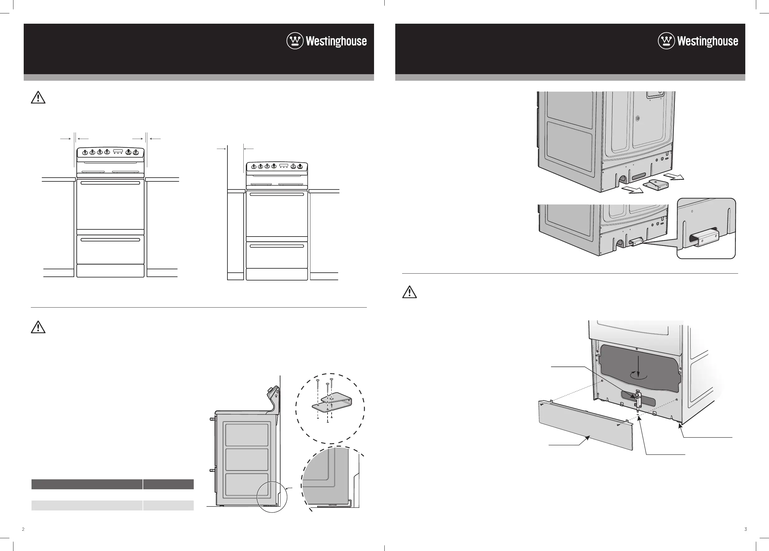
Installation dimensions
5mm
clearance
min.
5mm
clearance
min.
596mm
INSTALLATION
The appliance must not be installed in a corner. It must be
installed at least 100mm from the side wall.
100mm
WALL
Stability bolt
Kick panel
ø6.5mm drilled
location hole
Front
adjustable feet
WARNING
Step 3: Stability bolt
1. Remove oven door – to be done by
qualified personnel only. For separate
grill models only. (Refer to procedure).
2. Remove screws from kick panel.
To remove kick panel lift kick panel
upwards to release the two Location
Tabs from the holes in the bottom of
the panel.
3. Position the cooker into the anti-tilt
bracket.
4. Remove the tape from the stability
bolt.
5. Rotate the stability bolt 180˚ clockwise
until it is pointing to the left like the
picture below.
6. The stability bolt should now be able
to drop to the floor.
7. Mark the position for the stability bolt
on the floor.
8. Pull the cooker out and drill the bolt
hole, using a 6.5mm masonry or
wood drill. Minimum 30mm deep for
concrete.
9. Reposition the cooker back into place,
then fit the stability bolt into the
drilled hole.
Step 2: Fixing anti-tilt bracket
Position the anti-tilt bracket so that it will
fully engage into the slot at the rear of the
cooker. The bracket is mounted centrally
at the rear of the cooker. Anchor the
bracket into position using appropriate
fasteners.
WARNING
Installers responsibility
In ALL cases the anti-tilt bracket MUST be securely
anchored to the floor with suitable fasteners, and the
stability bolt fixed.
The anti-tilt bracket is a mandatory safety restraint.
In order to prevent accidental tipping of the appliance;
for example by a child climbing onto the open door, the
anti-tilt bracket supplied with the cooker MUST be installed.
ALWAYS ensure that the cooker is located so that the
anti-tilt bracket is engaged into the cooker.
The unit must be pushed up against the wall on installation.
On gas units check that the gas hose, if used, has not been
kinked during installation.
The following table outlines the distance between the
floor supporting the product and the surface supporting
the cooking vessel:
SURFACE TYPE (SUPPORTING VESSEL) DISTANCE (MM)
Coil 925
Ceramic 913
AA
Detail A
3 Fasteners
Minimum
3 fasteners
Detail A
Step 1: Positioning
Choose the most practical bracket mounting option for
your cooker. The anti-tilt bracket can be floor mounted or
floor and skirting mounted depending on the location of
the range plug/socket/connection.
 Loading...