WESTLOCK CONTROLS
280N MIDLAND AVENUE, STE.258, SADDLE BROOK, NJ 07663 TEL: 201-794-7650 FAX: 201-794-0913
www.westlockcontrols.com
12/20/2017 TECH-533/ D.W.O. 22902 Page 15 of 20
5 Field Wiring
Field Wiring Terminal Strip:
10) Blue wire Input (-) 4-20mA
9) Brown wire Input (+) 4-20mA
8) Yellow transmitter ( no polarity)
7) Yellow transmitter ( no polarity)
Terminal screw torque: 2 – 3 in. lb. (0.22 - 0.3 Nm)
Wires must be rated at least 105
°
C with minimum 0.25mm thickness shall be used for external
connections.
See Controlled Diagram (Appendix A - page 18)
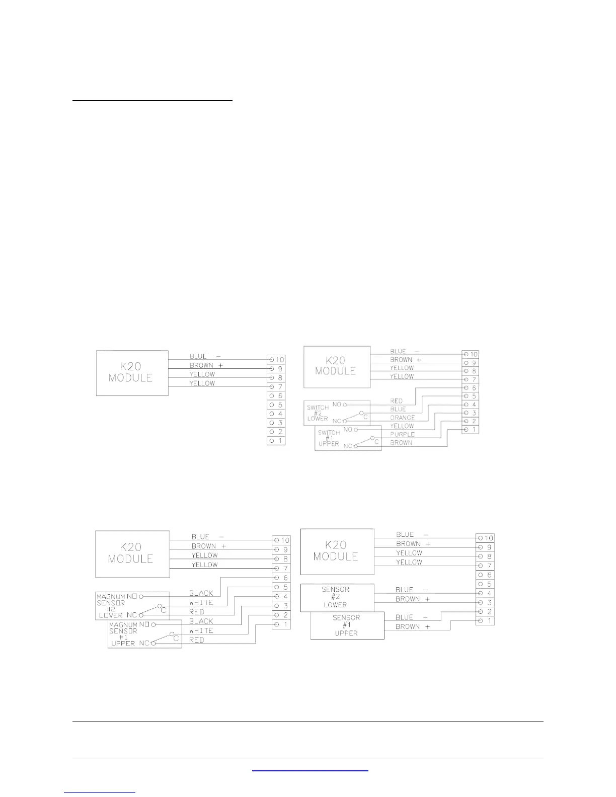
Wiring Diagrams:
Figure 7 No Switch option Figure 8 SPDT mechanical switches
Figure 9 SPDT Magnum proximity switch Figure 10 Inductive proximity sensors