Do you have a question about the Westlock K20 and is the answer not in the manual?
Details the certifications and standards the K20 positioner complies with, including ATEX and IECEX.
Critical safety warnings regarding ignition risk, static charge, and wiring requirements for the K20.
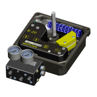
Provides an overview of the K20 as a 4-20mA electro-pneumatic valve positioner/controller.
Explains how the K20 utilizes keys, LCD, and Hall Effect sensing for auto calibration and operation.
Highlights key features like LCD display, auto calibration, manual tuning, and limit switches.
Details the mounting options and considerations for the K20 positioner and actuator.
Describes how to connect pneumatic lines for single and double acting actuators.
Guides users through setting the 4mA closed and 20mA open positions for auto calibration.
Explains how to perform auto calibration for input currents other than 4mA for fail position.
Details auto calibration for input currents other than 20mA for span position.
Allows users to manually adjust various parameters like gain, zero, span, and acting direction.
Describes how to adjust the gain applied when the valve opens.
Describes how to adjust the gain applied when the valve closes.
Explains how to enable or disable drop off at the end of travel.
Details how to adjust the electronic stop position for the closed state.
Details how to adjust the electronic stop position for the open state.
Explains how to select the valve's operating direction based on loop current.
Specifies the transmitter fault current output for failure indication.
Allows setting the timeout duration for calibration steps.
Explains how to save or discard changes made during calibration.
Describes how to cancel an ongoing auto calibration process.
Provides steps to reset the device to its original factory default settings.
| Shaft Material | Stainless Steel |
|---|---|
| Housing Material | Aluminum |
| Operating Temperature | -40°C to 85°C (-40°F to 185°F) |
| Ingress Protection | IP66 |
| Output Pressure | Equal to supply pressure |
| Ambient Temperature Range | -40°C to 85°C (-40°F to 185°F) |