18
E SERIES INSTALLATION MANUAL
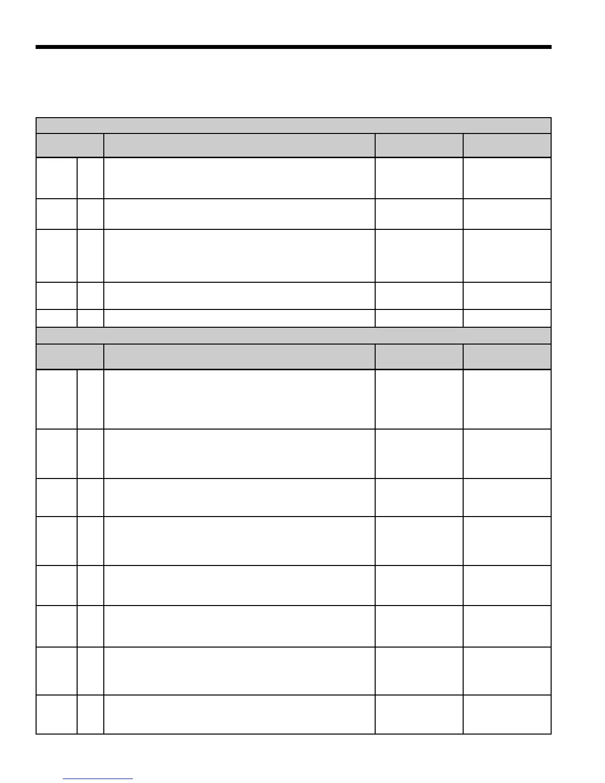
Standard Microprocessor DIP Switches
Prior to powering unit, ensure that all DIP switches on SW2 & SW3 are set properly according to the tables below.
FACTORY SETUP DIP SWITCHES (SW3)
DIP SWITCH
NUMBER
DESCRIPTION OFF POSITION ON POSITION
SW 3- 1
Dual Capacity/Single-Speed
Configures the control for single-speed compressor operation or
dual capacity operation.
Dual Capacity
Operation
Single-Speed
Operation
SW 3- 2
ECM2
Must be in the “ON” position.
Does Not Apply
Normal
SW 3- 3
No RPM/RPM
Configures the control to monitor the RPM output of an ECM/
ECM2 blower motor. When using IntelliZone or a PSC fan motor,
the control should be configured for “NO RPM” sensing.
PSC Fan/RPM
Monitoring Dis-
abled
ECM-ECM2 Fan/
RPM Monitoring
Enabled
SW 3- 4
Electric heat
Must be in the “ON” position to engage auxiliary heat.
No Aux Heat
Normal
SW 3- 5 Future Use Future Use Future Use
FIELD SELECTION DIP SWITCHES (SW2)
DIP SWITCH
NUMBER
DESCRIPTION OFF POSITION ON POSITION
SW 2- 1
Service Test Mode
On the control, allows field selection of “NORMAL” or “TEST” op-
erational modes. Test mode accelerates most timing functions 16
times to allow faster troubleshooting. Test mode also allows view
-
ing the “CURRENT” status of the fault inputs on the LED display.
Test Mode
Normal Speed
Operation
SW 2- 2
Freeze Protection Setting
Allows field selection of freeze thermistor fault sensing tempera
-
tures for well water (30°F) or antifreeze-protected (15°F) earth
loops.
Loop Water
Freeze Protection
15° F
Well Water
Freeze Protection
30° F
SW 2- 3
Accessory Relay
Allows field selection of the accessory relay to operate with the
compressor or fan.
Acc Relay Tracks
Fan
Acc Relay Tracks
Compressor
SW 2- 4
Fan Speed Control
Allows field selection of reduced fan speed (85% of selected
medium and high speed – ECM only) for cooling in the dehumidi-
fication mode.
Dehumidification
Fan Speeds
Normal Fan
Speeds
SW 2- 5
Auxiliary Off
Disables 3rd-stage Heating. Full emergency heat would still be
available if needed.
Disable Heating
Stage 3
Enable Heating
Stage 3
SW 2- 6
Diagnostics Inputs
Allows viewing the inputs from the thermostat to the control board
such as Y1, Y2, O, G, W, SL1-In on the LED display.
Diagnostic Inputs
Viewed at LEDs
Normal Display
Viewed at LEDs
SW 2- 7
Diagnostics Outputs
Allows viewing the outputs from the control board such as com-
pressor, reversing valve, blower, hot water pump, and loop pump
on the LED display.
Diagnostic Out-
puts Viewed at
LEDs
Normal Display
Viewed at LEDs
SW 2- 8
Thermostat Selection
Allows field selection of the type of thermostat being connected to
the control. The DIP switch should be in the OFF position.
24 VAC
Thermostats
TA32E12
Thermostat