14
E SERIES INSTALLATION MANUAL
Fan Performance Data
ECM2
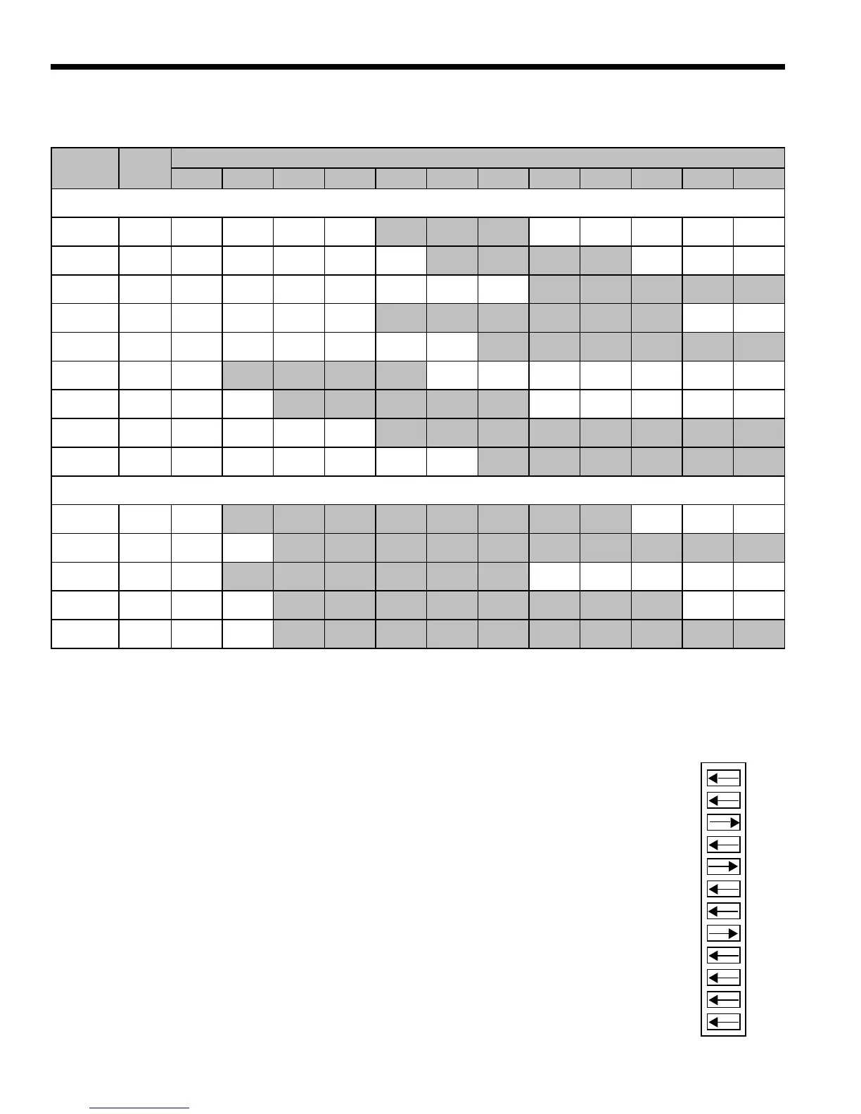
A 12-position DIP switch package on the control allows the airflow levels to be set for low,
medium, and high speed when using the ECM2 blower motor. Only three of the DIP switches
can be in the "on" position.
The first "on" switch (the lowest position number) determines the low speed fan setting.
The second "on" switch determines the medium speed fan setting.
The third "on" switch determines the high speed fan setting.
The example to the right shows SW1 on the control board configured for the following E040
airflow settings.
Low Speed Fan: 850 CFM
Medium Speed Fan: 1050 CFM
High Speed Fan: 1325 CFM
•
•
•
MODEL
MAX
ESP
AIR FLOW DIP SWITCH SETTINGS
1 2 3 4 5 6 7 8 9 10 11 12
SINGLE SPEED
E024 0.50 300 400
500
L
600
M
700
L
800
E030 0.50 300 400
500
L
600
700
M
800
900
H
1000
E035 0.50 500 600
700
L
800
900
M
1000
1100
H
1175 1250
E040 0.50 650 750
850
L
950
1050
M
1150 1250
1325
H
1375 1475
E047 0.50 650 750 850 950
1050
L
1150
1250
M
1325 1375 1475
1550
H
1600
E040
w/ 1 HP*
0.75
800
L
1000
M
1100
1300
H
1500
E047
w/ 1 HP*
0.75 800
1000
L
1100
1300
M
1500
H
1600 1800
E058 0.75 750 900 1000
1200
L
1400
M
1600 1700
1850
H
2000 2200 2300 2400
E066 0.75 750 900 1000 1200
1400
L
1600
1700
M
1850 2000
2200
H
2300 2400
DUAL CAPACITY
E036 0.50
600
L
700
800
M
900 1000 1100
1200
H
1300 1400 1500 1550 1600
E048 0.50
600
L
700 800 900
1000
M
1100 1200 1300 1400
1500
H
1550 1600
E048
w/ 1 HP*
0.75
750
L
900
1000
M
1200 1400
1600
H
1700 1850 2000 2200 2300 2400
E060 0.75
750
L
900 1000
1200
M
1400 1600 1700 1850
2000
H
2200 2300 2400
E072 0.75
750
L
900 1000 1200
1400
M
1600 1700 1850 2000
2200
H
2300 2400
Notes: * With optional 1 HP fan motor.
Factory settings are at recommended L-M-H DIP switch locations. M-H settings must be located within shaded CFM range. CFM is controlled
within ± 5% up to the maximum ESP. Max ESP includes allowance for wet coil and standard filter. Lowest and highest dip switch setting are as-
sumed to be L and H speed, respectively.