P83134 G
Sheet 3 of 6
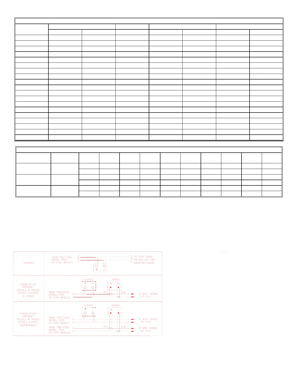
Table 3A: Vertical Plane
Vertical 15cd 15cd* 30cd 75cd
Angle (in deg.) UL Min.** Typ. 15cd Typ. 15cd* UL Min.** Typ. 30cd UL Min.** 75cd
0 15.0 21 100 30.0 42 75.0 90
5 13.5 21 100 27.0 42 67.5 88
10 13.5 21 100 27.0 42 67.5 87
15 13.5 20 100 27.0 40 67.5 83
20 13.5 19 100 27.0 38 67.5 79
25 13.5 19 98 27.0 38 67.5 74
30 13.5/11.3 18 96 27.0/22.5 36 67.5/56.3 70
35 9.8/11.3 18 94 19.5/22.5 36 48.8/56.3 68
40 6.9/11.3 16 92 13.8/22.5 32 34.3/56.3 66
45 5.1/11.3 14 90 10.2/22.5 28 25.5/56.3 63
50 4.0/8.3 12 84 8.1/16.5 24 20.0/41.3 59
55 3.3/6.8 12 77 6.6/13.5 24 16.3/33.8 54
60 2.7/6.0 9 70 5.4/12.0 18 13.5/30.0 52
65 2.4/5.3 8 63 4.8/10.5 16 12.0/26.3 40
70 2.3/5.3 8 56 4.5/10.5 16 11.3/26.3 31
75 2.0/4.5 8 50 4.0/9.0 16 10.0/22.5 29
80 1.8/4.5 8 30 3.6/9.0 16 9.0/22.5 29
85 1.8/3.8 8 20 3.6/7.5 16 9.0/18.8 28
90 1.8/3.8 8 8 3.6/7.5 16 9.0/18.8 24
Table 4: Typical Flashes Per Second Across Rated Voltage Range
Nominal Input Candela
Voltage Volts 20.0 22.0 24.0 26.0 28.0 31.0 10.5 12.0 15.6
24VDC 15cd, 30cd DC 1.0 1.1 1.3 1.4 1.5 1.7 ---- ---- ----
15cd* FWR 1.0 1.1 1.3 1.4 1.5 1.7 ---- ---- ----
24VDC 75cd DC 1.1 1.2 1.3 1.3 1.4 1.5 ---- ---- ----
FWR 1.0 1.1 1.2 1.3 1.3 1.4 ---- ---- ----
12VDC 15cd, 30cd DC ---- ---- ---- ---- ---- ---- 0.9 1.0 1.6
15cd* FWR ---- ---- ---- ---- ---- ---- 0.9 1.0 1.5
Note: ADA guidelines presently specify a flash rate of 1 to 3 flashes per second.
* 15cd models are UL Listed at 15cd and meet 75cd on axis.
** Wall/Ceiling
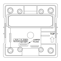
WIRING INFORMATION:
Figure 1: Wiring Diagrams
Figure 2.
1. All Strobe Appliances have in-out wiring terminals that
accepts two #12 to 18 American Wire Gauge (AWG)
wires at each screw terminal. Strip leads 3/8 inches and
connect to screw terminals.
2. Break all in-out wire runs on supervised circuits to
assure integrity of circuit supervision as shown in
Figure 2. Strobe/Plate assembly has two red leads and
two black leads for in-out wiring. The polarity shown
in the wiring diagrams is for the operation of the
appliances. The polarity is reversed by the FACP
during supervision.