P83134 G
Sheet 5 of 6
CAUTION: Check that the installed product will have sufficient clearance and wiring room prior to installing backboxes and
conduit, especially if sheathed multiconductor cable or 3/4" conduit fittings are used.
1. RS models can be flush mounted to a standard single-gang backbox (Figure A), 4” backbox (Figure B) or double-gang backbox
(Figure C). RS models can also be surface mounted to a 4” backbox (Figure B), double-gang backbox (Figure C) or the SHBB
(Figure D). RSP models can be flush mounted to a 4” backbox (Figure E) or surface mounted to a SBL-2 backbox (Figure F).
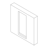
2. RS models are equipped with a Strobe Mounting Plate (SMP).
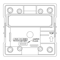
3. Mount the Strobe Mounting Plate (SMP) first to the backbox (note the lettering “Top” vertical strobe as marked). Next slide the
Beauty Plate over the Strobe Mounting Plate until the 2 side snaps of the Beauty Plate engage with the Strobe Mounting Plate.
Wheelock recommends orienting the Beauty Plate so that the FCC compliance label is positioned at the top of the strobe.
4. The Beauty Plate can be removed from the strobe assembly once engaged. First, gently insert a screwdriver into one of the slots
located on the side edges of the Beauty Plate. Second, gently pull away from the wall with the inserted screwdriver to disengage
the snap. Third, repeat the first and second steps for the second slot. Finally, gently lift the Beauty Plate away from the Strobe
Mounting Plate.
5. Mounting hardware for each mounting option is supplied.
6. Conduit entrances to the backbox should be selected to provide sufficient wiring clearance for the installed product.
7. When terminating field wires, do not use more lead length than required. Excess lead length could result in insufficient wiring
space for the signaling appliance.
8. Use care and proper techniques to position the field wires in the backbox so that they use minimum space and produce minimum
stress on the product. This is especially important for stiff, heavy gauge wires and wires with thick insulation or sheathing.
9. Do not pass additional wires (used for other than the signaling appliance) through the backbox. Such additional wires could
result in insufficient wiring space for the signaling appliance.
10. All models are UL Listed for indoor use with a temperature range of +32
o
F to +120
o
F (0
o
C to +49
o
C) and maximum humidity
of 85% RH.
WARNING: WHEN INSTALLING STROBES IN AN OPEN OFFICE OR OTHER AREAS CONTAINING PARTITIONS OR
OTHER VIEWING OBSTRUCTIONS, SPECIAL ATTENTION SHOULD BE GIVEN TO THE LOCATION OF THE STROBES
SO THAT THEIR OPERATING EFFECT CAN BE SEEN BY ALL INTENDED VIEWERS, WITH THE INTENSITY, NUMBER,
AND TYPE OF STROBES BEING SUFFICIENT TO MAKE SURE THAT THE INTENDED VIEWER IS ALERTED BY
PROPER ILLUMINATION, REGARDLESS OF THE VIEWER'S ORIENTATION. FAILURE TO DO SO COULD RESULT IN
PROPERTY DAMAGE AND SERIOUS INJURY OR DEATH TO YOU AND/OR OTHERS.
WARNING: A SMALL POSSIBILITY EXISTS THAT THE USE OF MULTIPLE STROBES WITHIN A PERSON'S FIELD
OF VIEW, UNDER CERTAIN CIRCUMSTANCES, MIGHT INDUCE A PHOTO-SENSITIVE RESPONSE IN PERSONS WITH
EPILEPSY. STROBE REFLECTIONS IN A GLASS OR MIRRORED SURFACE MIGHT ALSO INDUCE SUCH A RESPONSE.
TO MINIMIZE THIS POSSIBLE HAZARD, WHEELOCK STRONGLY RECOMMENDS THAT THE STROBES INSTALLED
SHOULD NOT PRESENT A COMPOSITE FLASH RATE IN THE FIELD OF VIEW WHICH EXCEEDS FIVE (5) Hz AT THE
OPERATING VOLTAGE OF THE STROBES (SEE TABLE 4). WHEELOCK ALSO STRONGLY RECOMMENDS THAT THE
INTENSITY AND COMPOSITE FLASH RATE OF INSTALLED STROBES COMPLY WITH LEVELS ESTABLISHED BY
APPLICABLE LAWS, STANDARDS, REGULATIONS, CODES AND GUIDELINES.
ANY MATERIAL EXTRAPOLATED FROM THIS DOCUMENT OR FROM WHEELOCK MANUALS OR OTHER
DOCUMENTS DESCRIBING THE PRODUCT FOR USE IN PROMOTIONAL OR ADVERTISING CLAIMS, OR FOR ANY
OTHER USE, INCLUDING DESCRIPTION OF THE PRODUCT'S APPLICATION, OPERATION, INSTALLATION AND
TESTING IS USED AT THE SOLE RISK OF THE USER AND WHEELOCK WILL NOT HAVE ANY LIABILITY FOR SUCH
USE.
NOTE: NFPA 72/ANSI 117.1 conform to ADAAG Equivalent Facilitation Guidelines in using fewer, higher intensity strobes within
the same protected area.
CAUTION: Check the installation instructions of the manufacturers of other equipment used in the system for any guidelines or
restrictions on wiring and/or locating Notification Alarm Circuits (NAC) and notification appliances. Some system communication
circuits and/or audio circuits, for example, may require special precautions to assure electrical noise immunity (e.g. audio crosstalk).
IMPORTANT: READ SEPARATE "GENERAL INFORMATION" SHEET FOR INFORMATION ON THE PLACEMENT,
LIMITATIONS, INSTALLATION, FINAL CHECKOUT, AND PERIODIC TESTING OF NOTIFICATION APPLIANCES.
NOTE: This equipment has been tested and found to comply with the limits for a Class B digital device, pursuant to Part 15 of the
FCC Rules. These limits are designed to provide reasonable protection against harmful interference in residential installation. This
equipment generates, uses and can radiate radio frequency energy and, if not installed and used in accordance with the instructions,
may cause harmful interference to radio communications. However, there is no guarantee that interference will not occur in a
particular installation. If this equipment does cause harmful interference to radio or television reception, which can be determined by
turning the equipment off and on, the user is encouraged to try to correct the interference by one or more of the following measures:
 Loading...