P82969 J
Sheet 3 of 3
UTA-WH SETTINGS:
The SW1 and SW2 switches of the UTA-WH are used to set input voltage and desired tone as shown in Figure 2 and Table 5. The
potentiometer R18 (shown in Figure 2) is used to adjust the volume of sound.
The factory settings are:
Input Voltage = 90Vrms/20-30Hz (SW1 POS 1 set on 0)
Tone = Horn (SW2 POS 1,3,4 set on 1,1,1 P0S 2 set on 0)
Volume = Maximum
Table 5: Input Voltage and Tone Selections
Switch Settings
Input Tone SW1 SW2
Voltage POS 1 POS 1 POS 2 POS 3 POS 4
Horn 1 1 0 1 1
24VDC/VAC Bell 1 1 0 1 0
and Vibrating Chime 1 1 0 0 0
48VDC Single Chime 1 1 1 0 1
No Sound 1 0 X X X
Horn 0 1 0 1 1
90Vrms/ Bell 0 1 0 1 0
20-30Hz Vibrating Chime 0 1 0 0 0
Single Chime 0 1 1 0 1
No Sound 0 0 X X X
X = Any Setting
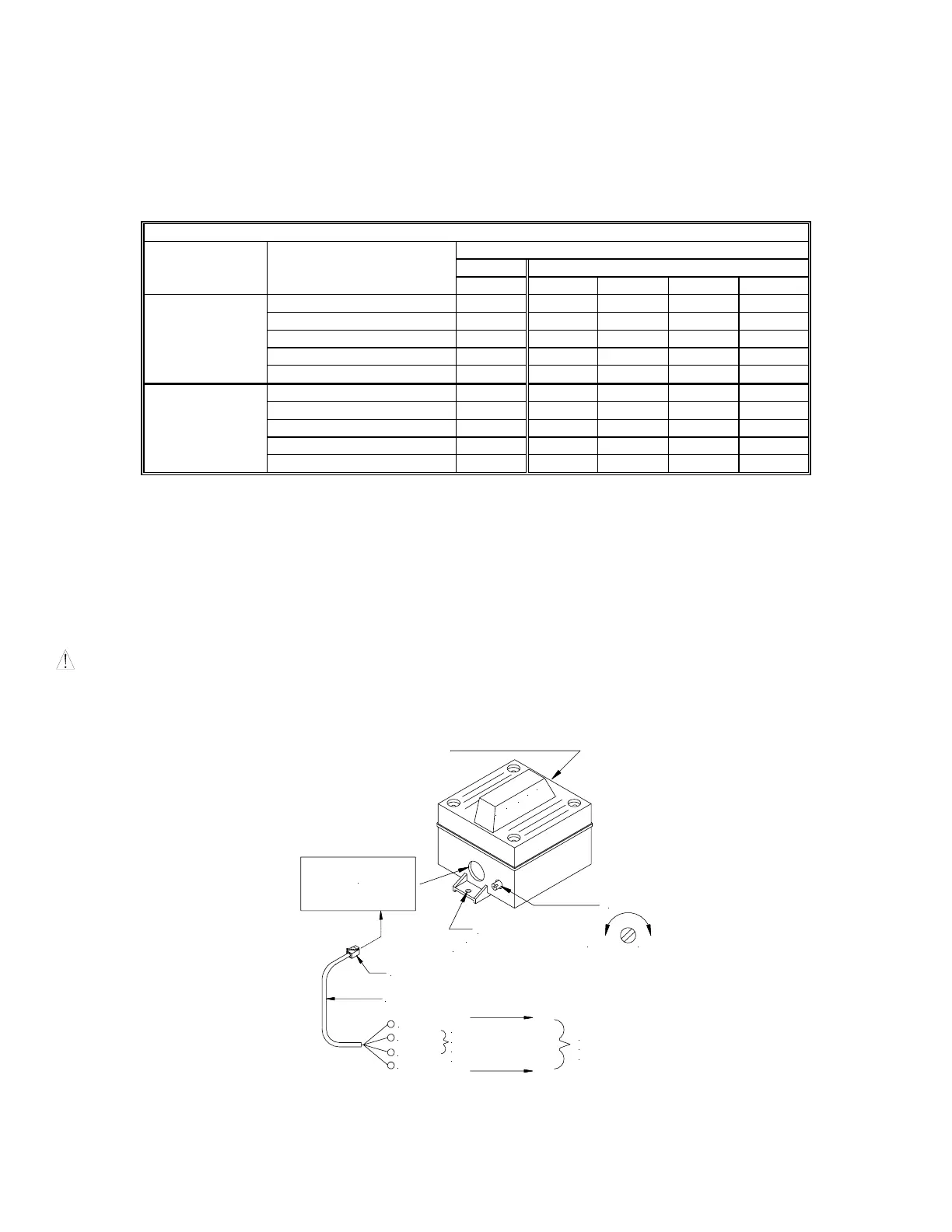
MOUNTING INFORMATION:
The UTA-WH is designed for mounting to walls, partitions or posts in both indoor and outdoor applications. Refer to Figures 1,2 and
3 for mounting, wiring and adjustment of each model. Use 4 conductor modular telephone line cords for ring voltage indoor wiring.
The UTA-WH provides terminal TB3 for 115VAC power connection. For outdoor applications, use conduit enclosed wiring.
Before mounting, test the appliance by temporarily connecting it as shown. Place a call into the system to make sure the appliance
operates properly.
WARNING: DO NOT STAND CLOSE TO THE UTA-WH WHEN TESTING OR OPERATING. TOO MUCH EXPOSURE AT
CLOSE RANGE MAY BE HARMFUL TO YOUR HEARING. UTA-WH SHOULD BE LOCATED AT LEAST 10 FEET AWAY
FROM LISTENERS.
Figure 1.
TWO 1/2" KNOCKOUTS IN TOP
FOR CONDUIT INSTALLATION
SCREW HOLES
(TOP AND BOTTOM)
MOUNTING
RJ11C
MODULAR JACK
INSTALL JACK COVER
(SUPPLIED) FOR
OUTDOOR USE
MODULAR PLUG
2 PAIR MODULAR LINE CORD
BLACK
RED
GREEN
YELLOW
TO COMMUNICATION
SYSTEM RING
VOLUME
SOFT LOUD
SIGNAL SUPPLY
90VRMS, 20Hz
24VDC/AC
OR
48VDC
P
H
O
N
E
 Loading...