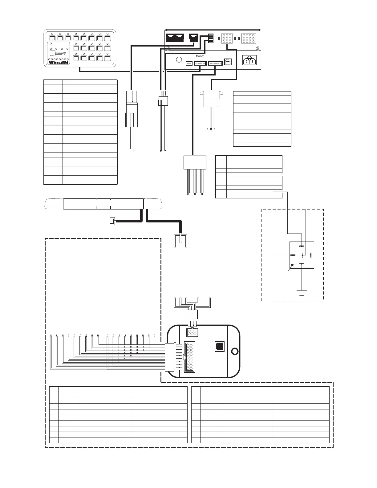
Example #1: Typical CenCom™ layout. Consult your CenCom manual before making any changes to this circuit.
1234567812345678
123
91234
11
22
3366
55
44
9912
8811
7710
WHITE
FUNCTION
Stand-by
Radio Repeat
Hands-Free
Wail
Yelp
Tone 3
Manual
Air Horn
Cruise
Horn Transfer Relay*
Low Power
Take down
Driver Alley
Passenger Alley
Override
Gun Lock*
All
External TA (if applicable)
External TA (if applicable)
-
Steady
Rear
Front
+ Flashing Take-downs
BUTTON
1
2
3
4
5
6
7
8
9
10
11
12
13
14
15
16
17
18
SS1
SS2
SS3
1
1234
9
14
5
10
15
6
11
16
7
12
17
8
13
18
23
*see your CenCom manual for details
COLOR
RED
ORG
N/C
WHT/BRN - Programable Input 1*
WHT/ - Programable Input 2*
WHT/ - Programable Input 3*
WHT/YEL - Programable Input 4*
BRN - Outlet 9 (250mA MAX)
RED - Outlet 10 (250mA MAX)
ORG - Outlet 11 (250mA MAX)
YEL - Outlet 12 (250mA MAX)*
POS
1
2
3
4
5
6
7
8
9
POS
POS
POS
POS
POS
POS
POS
POS
POS
TYCO-P&B P/N:
VF4-45F11
To
Car
Horn
From Vehicle
Horn Relay
Horn Ring
Transfer Relay
(Customer Supplied)
To
Outlet
#12
To
Input
#4
30
87A
85
86
87
Outlet 2 (20A MAX)
Outlet 1 (40A MAX)
Outlet 3 (20A MAX)
Connector A
Connector E
Connector D
Connector B (Blue)
Connector C (Green)
COLOR
BR N Output 8
*
RED
ORG
N/C
BLU
N/C
OW -
Isolated Relay - N.O. (10A MAX)
- Output 8
Isolated Relay - N.C. (10A MAX)*
- Output 8
Isolated Relay - Com. (10A MAX)*
GRN - Outlet 7 (10A MAX)
- Outlet 6 (10A MAX)
VIO - Outlet 5 (10A MAX)
GRY - Outlet 4 (10A MAX)
POS
1
2
3
4
5
6
7
8
9
POS
POS
POS
POS
POS
POS
POS
POS
POS
*see your CenCom manual for details
*see your CenCom manual for details
COLOR
GREEN
GRN/WHT
GRN/BLK
WHT/RED
WHITE
YELLOW
WHT/VIO
WHT/GRN
WHT/ORG
FUNCTION
FRONT PATTERN 1
FRONT PATTERN 2
FRONT PATTERN 3
FRONT PATTERN 4
DRIVER ALLEY
PASSENGER ALLEY
AUX
RIGHT TRAFFIC ADVISOR
CRUISE LIGHTS
Connects to CenCom...
Connector
D - PIN#7 (VIO)
D - PIN#6 (BLU)
O
O
E - PIN#5 (BRN)
B
Optional
Optional
Optional
Connector
Connector
ptional
ptional
Connector
POS
1
2
3
4
5
6
7
8
9
COLOR
BLUE
BLU/WHT
BLU/BLK
WHT/BRN
WHT/BLK
WHT/BLU
RED/WHT
WHT/YEL
VIOLET
FUNCTION
REAR PATTERN 1
REAR
REAR
REAR
TAKE DOWNS
FLASHING TD / ALLEY
PATTERN OVERRIDE
LEFT TRAFFIC ADVISOR
LOW POWER
PATTERN 2
PATTERN 3
PATTERN
-
Connects to CenCom...
Connector
Connector
Connector D - PIN#5 (GRN)
OPTIONAL
Connector
A
Optional
Optional
Optional
D - PIN#8 (GRY)
Connector C
E - PIN#6 (RED)
POS
10
11
12
13
14
15
16
17
18
LIGHTBAR
Communication
Cable
Power
Cable
Pos. 1 - (GRN) Front Pattern 1
Pos.10 - (BLU) Rear Pattern 1
Pos. 2 - (GRN/WHT) Front Pattern 2
Pos.11 - BLU/WHT) Rear Pattern 2
Pos. 3 - (GRN/BLK) Front Pattern 3
Pos.12 - (BLU/BLK) Rear Pattern 3
Pos. 4 - (WHT/RED) Front Pattern 4
Pos.13 - (WHT/BRN) Rear Pattern 4
Pos. 5 - (WHT) Driver Alley Light
Pos.14 - (WHT/BLK) Take-downs
Pos. 6 - (YEL) Passenger Alley Light
Pos.15 - (WHT/BLU) Flashing TD & Alley
Pos. 7 - (WHT/VIO) Aux
Pos.16 - (RED/WHT) Steady Override
Pos. 8 - (WHT/GRN) Traffic Advisor / RIGHT
Pos.17 - WHT/YEL) Traffic Advisor™ / LEFT
Pos. 9 - (WHT/ORG) Cruise Light
Pos.18 - (VIO) Low Power
9
8
7
6
5
4
3
2
1
18 17
16
15
14
13
12 11 10
321
654
Connect to an ignition
controlled circuit that
can accommodate an
additional 250mA load.
*
Pos. 1 - (RED) To +12VDC*
Pos.2-No
Connection
Pos. 3 - (BLK) To Ground
Pos. 4 - (GRN) COMM. A
Pos. 5 - (BLK/WHT) Shield
Pos. 6 - (GRY) COMM. B
RED - to +12VDC
(see lightbar manual for fusing)
BLACK - to CHASSIS GROUND
 Loading...